
Core Framework
Core Framework
This document describes the core framework components, key class structures and important methods of FastBee-Arduino in detail, providing developers with an in-depth implementation reference.
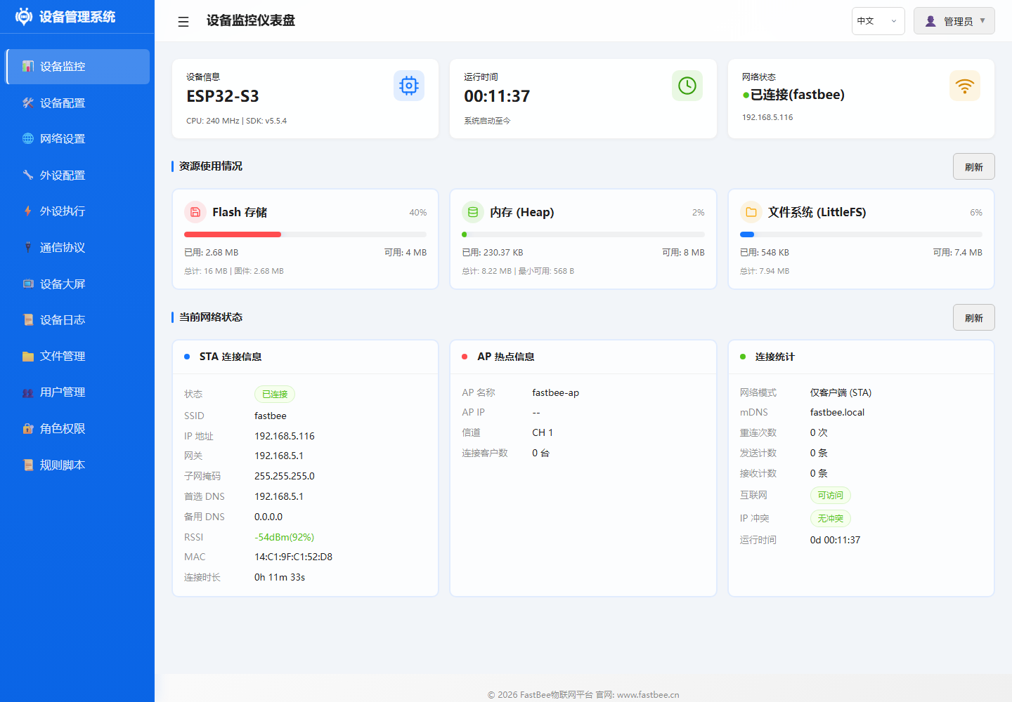
The main modules of the core framework map to the Status, Peripherals, Rules and Files capabilities in the Web console. When debugging the framework lifecycle, it is recommended to observe the dashboard resources, peripheral list, peripheral exec rules and file system status simultaneously.
| ID | Name | Type | Pins | Status | Actions |
|---|---|---|---|---|---|
adc | ADC Analog Conversion | ADC | 36 | Disabled | Edit / Enable / Delete |
can | CAN Bus | CAN | 4, 5 | Disabled | Edit / Enable / Delete |
i2c | I2C Bus | I2C | 17, 18 | Disabled | Edit / Enable / Delete |
jtag | JTAG Debug Interface | JTAG | 12, 13, 14, 15 | Disabled | Edit / Enable / Delete |
modbus_rtu | Modbus RTU - Industrial Device | UART | 16, 17 | Disabled | Edit / Enable / Delete |
oled_ssd1306_c3 | OLED Display - SSD1306 | LCD | 5, 6 | Disabled | Edit / Enable / Delete |
gpio_pwm | PWM Output | PWM Output | 21 | Disabled | Edit / Enable / Delete |
sdio | SD Card SDIO Interface | SDIO | 14, 15, 2, 4, 12, 13 | Disabled | Edit / Enable / Delete |
swd | SWD Debug Interface | SWD | 13, 14 | Disabled | Edit / Enable / Delete |
uart | UART Serial | UART | 16, 17 | Disabled | Edit / Enable / Delete |
| Name | Status | Trigger | Target Peripheral | Action | Stats | Actions |
|---|---|---|---|---|---|---|
| ADC Voltage Collection Report | Disabled | Timer Trigger | ADC Analog Conversion | Sensor Data Read -> ADC Analog Conversion | Trigger Count: 1 | Execute Once / Edit / Enable / Delete |
| ADC Voltage Below 2.30V Close Relay | Disabled | Event Trigger | - | Set Low Level | Trigger Count: 1 | Execute Once / Edit / Enable / Delete |
| ADC Voltage Above 2.50V Open Relay | Disabled | Event Trigger | - | Set High Level | Trigger Count: 1 | Execute Once / Edit / Enable / Delete |
| ADC Voltage Display on 7-Segment | Disabled | Timer Trigger | - | Display Number | Trigger Count: 1 | Execute Once / Edit / Enable / Delete |
| NTP Time Sync | Disabled | Platform Trigger (MQTT) | - | NTP Sync | Trigger Count: 1 | Execute Once / Edit / Enable / Delete |
| OLED Temp/Humidity Display | Disabled | Timer Trigger | - | OLED Custom Display | Trigger Count: 1 | Execute Once / Edit / Enable / Delete |
| OLED Custom Display - Button Trigger Device Info | Disabled | Event Trigger | - | OLED Custom Display | Trigger Count: 1 | Execute Once / Edit / Enable / Delete |
| OLED Custom Display - Timer Mixed | Disabled | Timer Trigger | - | OLED Custom Display | Trigger Count: 1 | Execute Once / Edit / Enable / Delete |
| OLED Custom Display - MQTT Message | Disabled | Platform Trigger (MQTT) | - | OLED Custom Display | Trigger Count: 1 | Execute Once / Edit / Enable / Delete |
| OTA Upgrade | Disabled | Platform Trigger (MQTT) | - | OTA Upgrade | Trigger Count: 1 | Execute Once / Edit / Enable / Delete |
The core service boundary diagram helps determine which module a feature should belong to: peripherals go to Peripheral, rules go to PeriphExec, networking goes to Network, platform and bus go to Protocols, files, logs and config go to system services.
FastBeeFramework Main Framework
FastBeeFramework is the core controller of the system, responsible for initializing all sub-modules and coordinating their work.
Initialization Flow
FastBeeFramework::getInstance()
  ├── loadConfig()              // Load all JSON configs from LittleFS
  ├── initPeripherals()         // Initialize all enabled peripherals
  ├── initNetwork()             // Start WiFi/network services and web server
  ├── initProtocols()           // Initialize MQTT/Modbus and other protocols
  ├── initPeriphExec()          // Start rule engine and async execution
  └── startHealthMonitor()      // Start health monitoring and memory gating
Key Methods
| Method | Description |
|---|---|
setup() | System boot entry point, calls all initialization methods in sequence |
loop() | Main loop, handles scheduled tasks and event dispatch |
getPeripheralManager() | Get peripheral manager instance |
getPeriphExecManager() | Get rule engine instance |
getProtocolManager() | Get protocol manager instance |
getNetworkManager() | Get network manager instance |
Lifecycle Management
Boot → setup() → Load Config → Init Modules → Enter loop()
                                    ↓
                              Handle Scheduled Tasks
                              Handle Network Events
                              Handle Protocol Messages
                              Health Monitor Check
                                    ↓
                              Continuous Operation (24/7)
PeriphExecManager Rule Engine
PeriphExecManager is the core module that implements "execute actions when conditions are met".
Rule Data Model
{
  "id": "exec_rule_01",
  "name": "Rule Name",
  "enabled": true,
  "execMode": 0,
  "triggers": [
    {
      "triggerType": 1,
      "triggerPeriphId": "dht_01",
      "timerMode": 0,
      "intervalSec": 10,
      "timePoint": "",
      "eventId": "",
      "operatorType": 0,
      "compareValue": "",
      "pollResponseTimeout": 1000,
      "pollMaxRetries": 2,
      "pollInterPollDelay": 100
    }
  ],
  "actions": [
    {
      "targetPeriphId": "relay_01",
      "actionType": 0,
      "actionValue": "",
      "useReceivedValue": false,
      "syncDelayMs": 0,
      "execMode": 0
    }
  ],
  "protocolType": 0,
  "scriptContent": "",
  "reportAfterExec": true
}
Trigger Types
| Type | Value | Name | Description | Key Fields |
|---|---|---|---|---|
| Platform Trigger | 0 | PLATFORM_TRIGGER | Triggered by MQTT downstream data | operatorType, compareValue |
| Timer Trigger | 1 | TIMER_TRIGGER | Periodic/fixed-time trigger | timerMode, intervalSec, timePoint |
| Event Trigger | 4 | EVENT_TRIGGER | System event/data source threshold | eventId, operatorType, compareValue |
| Poll Trigger | 5 | POLL_TRIGGER | Modbus/local data condition | triggerPeriphId, poll config |
Trigger Relationship: Multiple triggers in the same rule have an OR relationship; any match triggers the rule.
Action Types
| Value | Enum Name | Category | actionValue Meaning |
|---|---|---|---|
| 0 | ACTION_HIGH | GPIO | Ignored, set target pin HIGH |
| 1 | ACTION_LOW | GPIO | Ignored, set target pin LOW |
| 2 | ACTION_BLINK | GPIO | Blink interval in ms (default 500) |
| 3 | ACTION_BREATHE | GPIO | Breathe cycle in ms (default 2000) |
| 4 | ACTION_SET_PWM | GPIO | PWM duty cycle 0-255 |
| 5 | ACTION_SET_DAC | GPIO | DAC output value 0-255 |
| 6 | ACTION_SYS_RESTART | System | Ignored, restart device after 500ms delay |
| 7 | ACTION_SYS_FACTORY_RESET | System | Ignored, format LittleFS then restart |
| 8 | ACTION_SYS_NTP_SYNC | System | Ignored, trigger NTP time sync |
| 10 | ACTION_CALL_PERIPHERAL | Peripheral | Call peripheral-specific method (JSON) |
| 13 | ACTION_HIGH_INVERTED | GPIO | Ignored, inverted HIGH (active LOW) |
| 15 | ACTION_SCRIPT | Script | Command script content |
| 19 | ACTION_SENSOR_READ | Sensor | Read parameters (JSON) |
| 21 | ACTION_TRIGGER_EVENT | Event | Trigger logical event |
| 24 | ACTION_DISPLAY_TM1637 | Display | TM1637 display parameters |
| 25 | ACTION_DISPLAY_OLED | Display | OLED display parameters |
| 26 | ACTION_DISPLAY_LCD | Display | LCD display parameters |
| 27 | ACTION_DISPLAY_ROTATE | Display | Rotate display parameters |
Action Relationship: Multiple actions in the same rule are executed sequentially in array order.
Sensor Read actionValue Format
actionType: 19 uses a JSON string to describe the read parameters:
{
  "periphId": "sht31_i2c",
  "sensorCategory": "SHT31",
  "dataField": "temperature",
  "sensorLabel": "Temperature",
  "unit": "C",
  "decimalPlaces": 1,
  "driverParams": {
    "addr": "0x44",
    "sda": 21,
    "scl": 22
  }
}
Common sensorCategory Values:
| sensorCategory | Output Fields | Resource Recommendation |
|---|---|---|
analog | voltage, value | Available on ESP32 |
digital | value | Available on ESP32 |
dht11 / dht22 | temperature, humidity | Available on ESP32 |
ds18b20 | temperature | Available on ESP32 |
ultrasonic | distance | Available on ESP32 |
current | current | Available on ESP32 |
voltage | voltage | Available on ESP32 |
SHT31 | temperature, humidity | Available on ESP32, lightweight I2C |
AHT20 | temperature, humidity | Available on ESP32, lightweight I2C |
BH1750 | illuminance | Available on ESP32, lightweight I2C |
BMP280 | temperature, pressure, altitude | Recommended esp32s3-F16R8 |
MPU6050 | accelX/Y/Z, temperature, gyroX/Y/Z | Recommended esp32s3-F16R8 |
Async Execution Engine
Worker Pool Architecture:
- Pre-created 3 async tasks (avoid runtime allocation)
- Minimum heap memory gate: 30KB
- Task stack size: 4KB (normal) / 8KB (script)
- Task priority: 0 (lowest)
Execution Flow:
Rule Triggered → Check Heap Memory (>30KB?)
       → Yes: Dispatch async task to Worker Pool
       → No: Log WARN, skip execution
       → Worker executes action sequence
       → Report execution result
Key Methods:
evaluateCondition(): Evaluate trigger conditionsdispatchAction(): Dispatch actions to executorexecuteRuleAsync(): Execute rule asynchronouslyonSensorData(): Handle sensor data events
PeripheralManager Peripheral Management
PeripheralManager manages the lifecycle of all peripherals.
Peripheral Configuration Model
{
  "id": "sensor_01",
  "name": "Sensor Name",
  "type": 38,
  "enabled": true,
  "pinCount": 1,
  "pins": [13, 255, 255, 255, 255, 255, 255, 255],
  "params": {}
}
Field Description:
id: Unique identifier for rule referencesname: Display nametype: Peripheral type enum valueenabled: Whether enabledpinCount: Number of pins usedpins: Pin array (255 means unused)params: Type-specific parameters
Common Peripheral Types
| type | Name | Description | Pin Count |
|---|---|---|---|
| 1 | UART | Serial / Modbus RTU | 2 (TX/RX) |
| 2 | I2C | I2C Bus | 2 (SDA/SCL) |
| 11 | GPIO_DIGITAL_INPUT | Digital Input | 1 |
| 12 | GPIO_DIGITAL_OUTPUT | Digital Output | 1 |
| 13 | GPIO_DIGITAL_INPUT_PULLUP | Pull-up Input (Button) | 1 |
| 14 | GPIO_DIGITAL_INPUT_PULLDOWN | Pull-down Input | 1 |
| 15 | GPIO_ANALOG_INPUT | ADC Analog Input | 1 |
| 17 | GPIO_PWM_OUTPUT | PWM Output | 1 |
| 18-20 | GPIO_INTERRUPT | Interrupt Input (rising/falling/both edges) | 1 |
| 21 | GPIO_TOUCH | Touch Input | 1 |
| 26 | ADC_INPUT | ADC Input (alias) | 1 |
| 36 | LCD | Display (SSD1306/SH1106) | 2 (I2C) |
| 37 | SDIO | SD Card Interface (placeholder) | 4-6 |
| 38 | SENSOR | Sensor (DHT/DS18B20/Ultrasonic etc.) | 1-2 |
| 41 | PWM_SERVO | Servo | 1 |
| 42 | STEPPER_MOTOR | Stepper Motor | 4-6 |
| 43 | ENCODER | Rotary Encoder | 2-3 |
| 44 | ONE_WIRE | One-Wire (DS18B20) | 1 |
| 45 | NEO_PIXEL | WS2812B RGB LED Strip | 1 |
| 47 | SEVEN_SEGMENT_TM1637 | TM1637 7-Segment Display | 2 (CLK/DIO) |
| 51 | MODBUS_DEVICE | Modbus Slave Device | 0 (UART) |
| 60 | DEVICE_EVENT | Logical Event Source | 0 |
Hardware Initialization Flow
1. Validate Pin Legality
   - Avoid GPIO6-11 (Flash pins)
   - GPIO34-39 are input-only
   - ADC2 unavailable when WiFi is active

2. Check Pin Conflicts
   - Same pin cannot be allocated twice
   - I2C devices can share SDA/SCL

3. Configure Pin Mode
   - pinMode(pin, INPUT/OUTPUT/INPUT_PULLUP)
   - ledcSetup() for PWM
   - adcAttachPin() for ADC

4. Initialize Peripheral Driver
   - Create corresponding Driver based on type
   - Call driver->begin(pins, params)

5. Register to Peripheral List
   - Add to m_peripherals map
   - Record pin occupation table
Key Methods:
addPeripheral(): Add a peripheralinitHardware(): Initialize hardwaresetupHardware(): Configure pinsremovePeripheral(): Remove a peripheralgetPeripheral(): Get peripheral instanceperformMaintenance(): Periodic maintenance (handle ISR interrupt queue)processInterruptQueue(): Take interrupt events from FreeRTOS queue and dispatch
Interrupt Handling Mechanism:
GPIO interrupts are safely passed from ISR context to the main loop via a FreeRTOS queue:
ISR Interrupt → xQueueSendFromISR(pin) → Main Loop performMaintenance() → processInterruptQueue() → handleInterrupt(pin)Sensor Data Cache
Sensor read actions write the most recent reading to a local cache:
// Cache key format
"sensor_cache:<periphId>:<dataField>"

// Examples
"sensor_cache:dht_01:temperature" → 28.5
"sensor_cache:dht_01:humidity" → 65.2
Cached data is used for:
- Event trigger condition evaluation
- Web interface real-time display
- MQTT data reporting
ConfigStorage Configuration Storage
ConfigStorage manages persistence of all configurations.
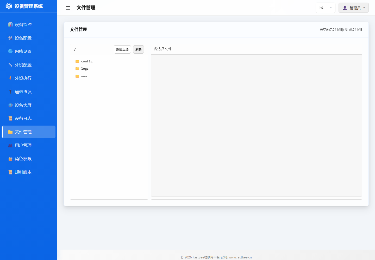
Configuration File Structure
/config/
  ├── device.json       # Device config (name/model/serial number)
  ├── network.json      # Network config (WiFi/Ethernet/4G)
  ├── peripherals.json  # Peripheral config (all peripheral list)
  ├── periph_exec.json  # Execution rules (triggers + actions)
  ├── protocol.json     # Protocol config (MQTT/Modbus)
  ├── rule_scripts.json # Rule scripts (Full)
  └── users.json        # User config (Full)
Storage Strategy
LittleFS File System:
- Embedded Flash file system
- Supports wear leveling
- Power-loss safe (atomic writes)
JSON Serialization:
- Uses ArduinoJson library
- Compact mode (reduces space usage)
- Stream read/write (avoids full loading)
Write Protection:
- Write to temporary file
.tmpfirst - Validate JSON format
- Atomically replace original file
- Preserve original config on failure
Config Import/Export
Export API:
GET /api/system/export-config?type=peripherals
GET /api/system/export-config?type=periph_exec
GET /api/system/export-config?type=all
Import API:
POST /api/system/import-config
Body: multipart/form-data (JSON file)
Key Methods:
loadConfig(): Load configurationsaveConfig(): Save configurationexportConfig(): Export configurationimportConfig(): Import configuration
HealthMonitor Health Monitoring
HealthMonitor continuously monitors system health status.
Monitoring Metrics
| Metric | Check Interval | Description |
|---|---|---|
| Free Heap Memory | 5s | ESP.getFreeHeap() |
| Max Allocatable Block | 5s | ESP.getMaxAllocHeap() |
| WiFi Connection Status | 1s | WiFi.status() |
| MQTT Connection Status | 1s | MQTTClient.connected() |
| System Uptime | Continuous | millis() |
Alert Mechanism
Memory Thresholds:
| Heap Memory | Action | Reason |
|---|---|---|
| < 20KB | WARN log | Alert low memory |
| < 10KB | Disable SSE | SSE connections use ~8KB |
| < 5KB | Reduce log level | Reduce string allocations |
Recovery Strategy:
- No auto-recovery (avoid frequent oscillation)
- Requires external intervention (restart/disable features)
- Logs alert messages for troubleshooting
WDT Watchdog
Configuration:
esp_task_wdt_init(10, true); // 10-second timeoutReasons:
- async_tcp file I/O may block
- Large JSON serialization is time-consuming
- Prevent system deadlock
Feeding:
- loop() main loop auto-feeds
- Async tasks need manual feeding
Boot Diagnostics
Output:
[BOOT] Chip: ESP32-WROOM-32U Rev3
[BOOT] Flash: 4096KB, PSRAM: 0KB
[BOOT] Cores: 2, Features: WiFi/BT/BLE
[BOOT] Free heap: 285432 bytes
[BOOT] Max alloc: 114688 bytes
[BOOT] PSRAM: disabled (no-PSRAM build)Purpose:
- Quickly determine if PSRAM is available
- Confirm available memory capacity
- Troubleshoot boot failures
Key Class Relationships
FastBeeFramework
  ├── PeripheralManager* m_peripheralManager
  ├── PeriphExecManager* m_periphExecManager
  ├── NetworkManager* m_networkManager
  ├── ProtocolManager* m_protocolManager
  ├── ConfigStorage* m_configStorage
  └── HealthMonitor* m_healthMonitor

PeripheralManager
  ├── map<string, Peripheral*> m_peripherals
  ├── map<int, bool> m_pinOccupancy
  └── vector<Driver*> m_drivers

PeriphExecManager
  ├── map<string, ExecRule*> m_rules
  ├── WorkerPool* m_workerPool
  ├── map<string, string> m_sensorCache
  └── ButtonEventSubsystem* m_buttonEvents

NetworkManager
  ├── WiFiManager* m_wifiManager
  ├── WebConfigManager* m_webManager
  └── NetworkAdapter* m_activeAdapter

ProtocolManager
  ├── MQTTClient* m_mqttClient
  ├── ModbusHandler* m_modbusHandler
  └── map<string, ProtocolHandler*> m_protocols
Related Documentation
- Architecture Design - Overall architecture and module relationships
- PeriphExec Flow - Complete rule engine business logic
- Peripheral Configuration Guide - All peripheral types in detail
- Development Guide - Adding new peripherals and protocols