
Peripheral Configuration
Peripheral Configuration
This document is based on source code
include/core/PeripheralTypes.h,src/core/PeripheralManager.cpp,data/config/peripherals.json,include/core/FeatureFlags.h,include/core/interfaces/ISensorDriver.h,include/core/DriverRegistry.handplatformio.ini, describing all types, pin requirements, parameter meanings, support status, and best practices supported by the peripheral configuration system.
Current Version Notes
- Lite environments (
esp32c3-F4R0,esp32c6-F4R0) retain UART/I2C/SPI, GPIO, basic sensors, OLED/TM1637, NeoPixel, and peripheral execution core capabilities. - Standard environments (
esp32-F4R0,esp32s3-F8R0) add Modbus, Command Script, RuleScript, RFID, IR, and more I2C sensors; Ethernet, 4G, file, logging, and user roles default to Full or custom build capabilities. - Peripheral configuration is saved to
/config/peripherals.json, which can be individually backed up and restored as "Peripheral Configuration" via Web "Configuration Import/Export". - Factory
data/config/peripherals.jsonis released as a safe template with hardware peripherals defaulting toenabled: false;enabled: truein documentation examples represents the target state after completing wiring verification. - For sensor data to serve as a peripheral execution event trigger source, you must first configure sensor collection actions in peripheral execution. The system caches collection results as
ds:<peripheralId>_<field>data sources. - Modbus sub-devices are managed by the communication protocol page, participate in device control and peripheral execution as virtual peripherals, and do not occupy local GPIO.
The Web entry for peripheral configuration is shown below. When adding new peripherals, first select the type, then fill in pins and type parameters; for batch migration, back up peripherals.json via file management or configuration import/export first.
| ID | Name | Type | Pins | Status | Actions |
|---|---|---|---|---|---|
adc | ADC Analog Converter | ADC | 36 | Disabled | Edit / Enable / Delete |
can | CAN Bus | CAN | 4, 5 | Disabled | Edit / Enable / Delete |
i2c | I2C Bus | I2C | 17, 18 | Disabled | Edit / Enable / Delete |
jtag | JTAG Debug Interface | JTAG | 12, 13, 14, 15 | Disabled | Edit / Enable / Delete |
modbus_rtu | Modbus RTU-Industrial Device | UART | 16, 17 | Disabled | Edit / Enable / Delete |
oled_ssd1306_c3 | OLED Display-SSD1306 | LCD | 5, 6 | Disabled | Edit / Enable / Delete |
gpio_pwm | PWM Output | PWM Output | 21 | Disabled | Edit / Enable / Delete |
sdio | SD Card SDIO Interface | SDIO | 14, 15, 2, 4, 12, 13 | Disabled | Edit / Enable / Delete |
swd | SWD Debug Interface | SWD | 13, 14 | Disabled | Edit / Enable / Delete |
uart | UART Serial Port | UART | 16, 17 | Disabled | Edit / Enable / Delete |
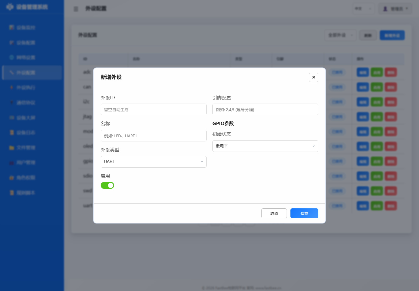
When integrating a new module, it is not recommended to enable immediately after batch importing from JSON. A more stable order is to first confirm hardware and version support, then save disabled configuration via the page, verify individual items, and then enter peripheral execution rules.
If you are unsure which type to select, first narrow the scope using the five entry categories above (digital, analog, bus devices, RS485 slaves, and display output), then return to the type ID table later in this document to confirm fields.
Peripheral configuration is not a single form field but a chain from Web forms, JSON files, validation logic, runtime drivers to rule consumers. After importing configuration on-site, it is recommended to check id, type, pins, params, enabled, and version capability switches in the order shown in the diagram, confirming each layer can explain the current runtime state.
| Peripheral Type | Required Fields | Key Parameters | Pre-Enable Check | Common Use |
|---|---|---|---|---|
| GPIO Output | id / type / pins[0] | initialState / invert | Load current vs relay level | LEDs, relays, buzzers |
| GPIO Input | id / type / pins[0] | pullup / debounce | Pull-up/down and debounce time | Buttons, PIR, switches |
| ADC / Analog | pins[0] / category | vRef / ratio / offset | Prefer ADC1, voltage within range | Voltage, current, light, rain |
| I2C Device | SDA / SCL / address | bus / frequency / driver | Address scan and pull-up resistors | OLED, SHT31, BH1750 |
| UART / RS485 | TX / RX / baudrate | parity / stopBits / dePin | A/B wiring and direction control | Modbus RTU, serial devices |
| Display Output | type / pins / address | width / height / brightness | Power, bus, display orientation | OLED, TM1637, LCD |
| Motion Control | pins / speed / limits | angle / steps / rpm | External power and mechanical limits | Servos, steppers, motors |
| Virtual Peripheral | id / source / mapping | eventId / slaveId / register | Reference chain and version capability | DeviceEvent, Modbus sub-devices |
If you only want to quickly determine which fields a peripheral type needs, check the parameter matrix first, then return to the type ID table and field descriptions later in this document. The "Pre-Enable Check" in the matrix serves as a field wiring checklist.
Table of Contents
- 1. Overview
- 2. Peripheral Type ID Mapping Table
- 3. Communication Interfaces
- 4. GPIO Interfaces
- 5. Analog Signal Interfaces
- 6. Debug Interfaces
- 7. Dedicated Peripherals
- 8. Modbus Peripherals
- 9. Virtual/Logical Peripherals
- 10. Configuration Structure and Fields
- 11. Feature Compile Flags (FeatureFlags)
- 12. FAQ and Troubleshooting
- 13. Best Practices
- 14. Sensor Driver Extension (ISensorDriver)
1. Overview
The peripheral configuration system adopts a three-layer model of "type-driven + pin occupation validation + runtime state":
- Configuration Layer:
data/config/peripherals.json, loaded from LittleFS on cold boot. - Management Layer:
PeripheralManagersingleton, responsible for CRUD, pin conflict detection, hardware initialization/teardown, and generic read/write interfaces. - Driver Layer: Dispatches to underlying implementations by type:
- GPIO series →
pinMode/digitalWrite/ledcWrite - I²C/SPI/UART →
Wire/SPI/Serial - LCD/OLED → U8g2 (
LCDManager) - TM1637 → Custom bit-bang (
SevenSegmentDriver) - Modbus → Delegated to
ModbusHandlervia callbacks
- GPIO series →
Convention: All hardware operations go through PeripheralManager uniformly; direct pinMode/digitalWrite in business code is prohibited to avoid pin occupation conflicts and state inconsistency.
Hardware Initialization and Teardown Behavior
When a peripheral is enabled, PeripheralManager::setupHardware() automatically performs hardware initialization; when disabled or deleted, teardownHardware() handles resource cleanup.
| Peripheral Type | Initialization Behavior (setupHardware) | Teardown Behavior (teardownHardware) |
|---|---|---|
| I2C (2) | Wire.begin(sda, scl, freq) | Wire.end() |
| SPI (3) | SPI.begin(sck, miso, mosi, cs) + CS pin OUTPUT/HIGH | SPI.end() + CS pin released as INPUT |
| DAC (27) | dacWrite(pin, defaultValue) | dacWrite(pin, 0) zero out |
| ADC (26) | analogReadResolution(res) + idle read to stabilize ADC | (No special cleanup needed) |
| PWM_SERVO (41) | ledcAttach(pin, freq, res) | ledcDetach(pin) + pin release |
| ONE_WIRE (44) | pinMode(pin, INPUT_PULLUP) enable internal pull-up | pinMode(pin, INPUT) release pull-up |
| SENSOR (38) | pinMode(pin, INPUT_PULLUP) + log | (No special cleanup needed) |
| RF_MODULE (48) | TX: OUTPUT + initial level; RX: INPUT | TX: restore default level |
| RADAR_SENSOR (49) | pinMode(pin, INPUT) | (No special cleanup needed) |
Note: CAN(4), USB(5), JTAG(31), SWD(32), CAMERA(39), ETHERNET(40) etc. are mainly configuration placeholders or chip-level fixed capabilities; SDIO(37) currently supports SPI lazy initialization; ENCODER(43) supports GPIO interrupt counting, see section 7.8.
2. Peripheral Type ID Mapping Table
| ID | Enum Constant | Category | Display Name | Implementation Status | Pin Count |
|---|---|---|---|---|---|
| 0 | UNCONFIGURED | —— | Unconfigured | Placeholder | 0 |
| 1 | UART | Communication | Serial port | ✅ Implemented | 2 (RX,TX) |
| 2 | I2C | Communication | I2C bus | ✅ Implemented | 2 (SDA,SCL) |
| 3 | SPI | Communication | SPI bus | ✅ Implemented | 4 (MISO,MOSI,SCK,CS) |
| 4 | CAN | Communication | CAN bus | ⚠️ Config framework ready, driver TODO | 2 |
| 5 | USB | Communication | USB interface | ⚠️ Config framework ready, driver TODO | 2 |
| 11 | GPIO_DIGITAL_INPUT | GPIO | Digital input | ✅ Implemented | 1 |
| 12 | GPIO_DIGITAL_OUTPUT | GPIO | Digital output | ✅ Implemented | 1 |
| 13 | GPIO_DIGITAL_INPUT_PULLUP | GPIO | Digital input (pull-up) | ✅ Implemented / Button default type | 1 |
| 14 | GPIO_DIGITAL_INPUT_PULLDOWN | GPIO | Digital input (pull-down) | ✅ Implemented | 1 |
| 15 | GPIO_ANALOG_INPUT | GPIO | Analog input | ✅ Implemented (analogRead) | 1 |
| 16 | GPIO_ANALOG_OUTPUT | GPIO | Analog output | ✅ Implemented (LEDC PWM analog) | 1 |
| 17 | GPIO_PWM_OUTPUT | GPIO | PWM output | ✅ Implemented (LEDC) | 1 |
| 18 | GPIO_INTERRUPT_RISING | GPIO | Interrupt (rising edge) | 🟡 ISR skeleton exists, event queue TODO | 1 |
| 19 | GPIO_INTERRUPT_FALLING | GPIO | Interrupt (falling edge) | 🟡 ISR skeleton exists, event queue TODO | 1 |
| 20 | GPIO_INTERRUPT_CHANGE | GPIO | Interrupt (change) | 🟡 ISR skeleton exists, event queue TODO | 1 |
| 21 | GPIO_TOUCH | GPIO | Capacitive touch | ⚠️ Chip dependent; ESP32 classic supports | 1 |
| 26 | ADC | Analog Signal | ADC | ✅ Implemented | 1 |
| 27 | DAC | Analog Signal | DAC | ✅ Implemented (GPIO25/26 only, ESP32 classic) | 1 |
| 31 | JTAG | Debug | JTAG debug | 🔘 Type marker only, chip-level fixed | 4 |
| 32 | SWD | Debug | SWD debug | 🔘 Type marker only, chip-level fixed | 2 |
| 36 | LCD | Dedicated | LCD/OLED display | ✅ Implemented (U8g2: SSD1306/SH1106 etc.) | 2+ |
| 37 | SDIO | Dedicated | SD card interface | 🟡 SPI mode lazy init; SDMMC GPIO init only | 6 |
| 38 | SENSOR | Dedicated | Generic sensor (DHT/DS18B20) | ✅ Implemented (FASTBEE_ENABLE_SENSOR_DRIVER) | 1 |
| 39 | CAMERA | Dedicated | Camera | ⚠️ Config framework ready, driver TODO | 8 |
| 40 | ETHERNET | Dedicated | Ethernet | ⚠️ Config framework ready, driver TODO | 4 |
| 41 | PWM_SERVO | Dedicated | Servo | ✅ Implemented (LEDC) | 1 |
| 42 | STEPPER_MOTOR | Dedicated | Stepper motor | ✅ Implemented (ULN2003 4-phase half-step, non-blocking Ticker) | 4 (IN1,IN2,IN3,IN4) |
| 43 | ENCODER | Dedicated | Encoder | ✅ GPIO interrupt counting implemented | 2 |
| 44 | ONE_WIRE | Dedicated | One-Wire | ✅ Implemented via SENSOR driver chain (DS18B20) | 1 |
| 45 | NEO_PIXEL | Dedicated | WS2812B LED/pixel strip | ✅ Implemented (ESP32 RMT, disabled by default) | 1 |
| 46 | RESERVED_46 | Compat reserved | Reserved | 🔒 Legacy buzzer type placeholder, UI no longer shows | 0 |
| 47 | SEVEN_SEGMENT_TM1637 | Dedicated | TM1637 4-digit display | ✅ Implemented (FASTBEE_ENABLE_SEVEN_SEGMENT) | 2 (CLK,DIO) |
| 48 | RF_MODULE | Dedicated | 433MHz RF module | ✅ Implemented (OOK/EV1527) | 1 |
| 49 | RADAR_SENSOR | Dedicated | Microwave radar sensor (RCWL-0516) | ✅ Implemented | 1 |
| 51 | MODBUS_DEVICE | Modbus | Modbus sub-device | ✅ Implemented (no GPIO occupied) | 0 |
| 60 | DEVICE_EVENT | Virtual | Device event emitter | ✅ Implemented (no hardware) | 0 |
Legend: ✅ Fully implemented and enabled by default / 🟡 Partially implemented / ⚠️ Config placeholder only / 🔒 Disabled by default / 🔘 Type marker only
3. Communication Interfaces
3.1 UART (type=1)
| Field | Meaning | Values |
|---|---|---|
pins[0] | RX (Receive) | Any valid GPIO |
pins[1] | TX (Transmit) | Any valid GPIO |
params.baudRate | Baud rate | 1 ~ 5000000, commonly 9600/115200 |
params.dataBits | Data bits | 5~8 |
params.stopBits | Stop bits | 1 or 2 |
params.parity | Parity | 0=None / 1=Odd / 2=Even |
Example:
{ "id": "uart0", "name": "Serial0-Debug", "type": 1, "enabled": true,
  "pins": [1, 3],
"params": { "baudRate": 115200, "dataBits": 8, "stopBits": 1, "parity": 0 } }Note: ESP32 defaults Serial to GPIO1/3 (USB debug). Modbus RTU typically uses Serial2 (GPIO16/17).
3.2 I2C (type=2)
| Field | Meaning | Values |
|---|---|---|
pins[0] | SDA | Recommended GPIO21 |
pins[1] | SCL | Recommended GPIO22 |
params.frequency | Clock frequency | Only 100000 / 400000 / 1000000 supported |
params.address | Slave address | 0~127, master mode is 0 |
params.isMaster | Is master | true (recommended) |
Example:
{ "id": "i2c", "name": "I2C Bus", "type": 2, "enabled": false,
  "pins": [21, 22],
  "params": { "frequency": 100000, "address": 0, "isMaster": true } }
3.3 SPI (type=3)
| Field | Meaning |
|---|---|
pins[0] | MISO |
pins[1] | MOSI |
pins[2] | SCK |
pins[3] | CS |
params.frequency | 1 ~ 80 MHz |
params.mode | 0~3 |
params.msbFirst | true = MSB first |
3.4 CAN / USB (Driver Not Implemented)
Configuration data will be saved, but setupHardware will print not yet implemented. Business layer must implement drivers before use.
4. GPIO Interfaces
4.1 Digital Input / Output (type=11~14)
| Type | Description | Typical Use |
|---|---|---|
11 GPIO_DIGITAL_INPUT | High-impedance input, external pull needed | Encoder A/B phases |
12 GPIO_DIGITAL_OUTPUT | Push-pull output | Relays, LEDs |
13 GPIO_DIGITAL_INPUT_PULLUP | Internal pull-up | Buttons (press to GND) |
14 GPIO_DIGITAL_INPUT_PULLDOWN | Internal pull-down | Buttons (press to VCC) |
Button Events: Only type=13/14 are scanned by
PeriphExecScheduler::checkButtonEvents, supportingbutton_click/button_double_click/button_long_press_2s/5s/10s.
4.2 Analog Input (type=15) / ADC (type=26)
- ESP32 classic: ADC1 (GPIO32~39) recommended for concurrent WiFi use; ADC2 conflicts with WiFi.
analogRead(pin)returns 0~4095 (12-bit).
4.3 PWM Output (type=17) / Analog Output (type=16) / Servo (type=41)
| Parameter | Description | Constraint |
|---|---|---|
pwmChannel | LEDC channel | 0 ~ CHIP_MAX_PWM_CH-1 (16 for ESP32) |
pwmFrequency | Frequency Hz | freq × 2^resolution ≤ 80MHz |
pwmResolution | Resolution bits | 1~16 |
defaultDuty | Default duty cycle | 0 ~ (2^resolution - 1) |
Frequency/Resolution Combination Limits (examples):
- 1kHz × 13 bits = 8.192M ✅
- 40kHz × 12 bits = 163.84M ❌
4.4 Interrupts (type=18/19/20)
Current implementation: isrHandler only records the trigger pin number; FreeRTOS queue dispatch to main loop is not yet implemented. Use button events (type=13/14) as an alternative.
4.5 Touch (type=21)
Only valid for chips with CHIP_HAS_TOUCH (ESP32 classic supports T0~T9).
5. Analog Signal Interfaces
5.1 DAC (type=27)
- Hardware Limitation: Only ESP32 classic GPIO25/26 have real DAC; other chips/pins will be rejected.
- Output range: 8-bit (0~255), corresponding to 0V~VDD.
5.2 ADC (type=26)
Equivalent to GPIO_ANALOG_INPUT, distinguished by params.attenuation (0~3) and params.resolution (9~12).
6. Debug Interfaces
JTAG=31 / SWD=32 are type marker positions. ESP32's JTAG pins are fixed at GPIO12~15; enabling them affects normal GPIO functionality of these pins.
7. Dedicated Peripherals
7.1 LCD/OLED Display (type=36)
Implementation Status: ✅ Fully implemented. Enabled by default in Lite / Standard / Full (
FASTBEE_ENABLE_LCD=1).
Supported Controllers (covered by U8g2 library):
- SSD1306 (128×64 / 128×32 OLED, I²C 0x3C)
- SH1106 (128×64 OLED)
- Other character/graphic LCDs supported by U8g2
Parameters:
| Field | Meaning | Values |
|---|---|---|
pins[0] | SDA (I²C) / MOSI (SPI) | |
pins[1] | SCL (I²C) / SCK (SPI) | |
pins[2] | CS (SPI only) | Optional |
pins[3] | DC (SPI only) | Optional |
params.width | Width | 128 |
params.height | Height | 64 / 32 |
params.interface | Interface | 0=Parallel / 1=SPI / 2=I2C (default) |
Example:
{ "id": "oled_display", "name": "OLED Display", "type": 36, "enabled": true,
  "pins": [23, 22],
  "params": { "width": 128, "height": 64, "interface": 2 } }
Related Rule Actions: ACTION_DISPLAY_CUSTOM (OLED custom display, supports multi-line text + variable interpolation). See oled-usage-guide.md.
7.2 TM1637 Seven-Segment Display (type=47)
Implementation Status: ✅ Implemented, custom bit-bang driver (
SevenSegmentDriver), enabled by default in Lite / Standard / Full.
| Field | Meaning |
|---|---|
pins[0] | CLK |
pins[1] | DIO |
params.brightness | Brightness 0~7 |
Constraint: CLK/DIO cannot share pins with other peripherals. Due to historical pin conflict issues with buttons, always allocate separate GPIOs for the seven-segment display.
7.3 Generic Sensor (type=38) / One-Wire (type=44)
| Subclass | Pins | Description |
|---|---|---|
| DHT11/DHT22 | 1 DATA | Temperature and humidity |
| DS18B20 | 1 DQ (1-Wire) | Temperature |
Read and cache via peripheral execution action ACTION_SENSOR_READ. Requires FASTBEE_ENABLE_SENSOR_DRIVER enabled (on by default).
7.4 Reserved (type=46)
The legacy dedicated buzzer type has been removed. type=46 is retained as a historical number only; the Web no longer provides an add entry.
7.5 WS2812B / NeoPixel LED (type=45)
Uses ESP32 RMT peripheral to send WS2812B GRB timing, without depending on third-party NeoPixel libraries. pins[0] connects to WS2812B's DIN; default test template is ws2812b, GPIO4, 1 LED, brightness 64, disabled by default.
| Field | Meaning | Default / Range |
|---|---|---|
pins[0] | DIN data pin | Valid output GPIO |
params.count | LED count | Default 1, max 64 |
params.brightness | Global brightness | Default 64, range 0~255 |
Peripheral execution controls via ACTION_CALL_PERIPHERAL:
| actionValue Example | Behavior |
|---|---|
{"periphId":"ws2812b","action":"color","value":"#ff0000"} | Display red |
{"periphId":"ws2812b","action":"off"} | Turn off |
{"periphId":"ws2812b","action":"rainbow"} | Advance one step through rainbow cycle |
{"periphId":"ws2812b","action":"brightness","value":"96"} | Set brightness |
7.6 Servo (type=41)
Uses LEDC 50Hz PWM, pulse width 0.5ms~2.5ms corresponding to 0°~180°.
7.7 Stepper Motor (type=42)
Designed for 28BYJ-48 + ULN2003 type 4-phase stepper motor driver boards. pins[0..3] connect to ULN2003's IN1, IN2, IN3, IN4 in order. The driver uses an 8-step half-step sequence with non-blocking Ticker output, avoiding long blocking of the Web service during peripheral execution actions.
| Field | Meaning | Default / Range |
|---|---|---|
pins[0] | IN1 | Valid GPIO |
pins[1] | IN2 | Valid GPIO |
pins[2] | IN3 | Valid GPIO |
pins[3] | IN4 | Valid GPIO |
params.stepsPerRevolution | Steps per revolution | Default 2048 |
params.speed | Default RPM | Default 8, max 30 |
Peripheral execution can control this peripheral via ACTION_CALL_PERIPHERAL, supporting forward, reverse, stop, faster, slower, setSpeed, direction and other actions.
Safety Reminder: GPIO9/10/11 on classic ESP32 are typically occupied by Flash SPI. The firmware will reject enabling stepper motors on reserved pins for the current chip to avoid restarts from misconfiguration. GPIO 11/10/9/13 are more suitable for ESP32-S3; classic ESP32 should use available free GPIOs.
7.8 SD Card / Encoder / Camera / Ethernet
Current implementation status:
| Type | Status | Description |
|---|---|---|
SDIO | 🟡 Partially implemented | SPI mode initializes CLK/MOSI/MISO/CS with lazy mount; SDMMC mode currently only does GPIO initialization and log prompts |
ENCODER | ✅ Implemented | Uses GPIO interrupt for A/B phase counting, supports reading counter status and resetting counter |
CAMERA | ⚠️ Placeholder | Configuration only, camera driver not integrated |
ETHERNET peripheral type | ⚠️ Placeholder | Peripheral type saves config only; real W5500 networking controlled by NetworkManager / EthernetAdapter and FASTBEE_ENABLE_ETHERNET |
7.9 RF Module (type=48)
433MHz OOK/EV1527 RF module, supporting transmit (TX) and receive (RX) modes.
Pin Requirements: 1 data pin (TX mode requires output-capable pin, RX mode can be input pin)
params Parameters:
| Field | Type | Default | Description |
|---|---|---|---|
| mode | uint8_t | 0 | 0=TX transmit, 1=RX receive level monitor |
| pulseWidth | uint16_t | 350 | Pulse width (microseconds) |
| repeat | uint8_t | 3 | Transmit repeat count |
| bitLength | uint8_t | 24 | Code bit length |
| activeHigh | bool | true | true: HIGH = RF active |
Hardware Initialization: TX mode sets pin as OUTPUT, RX mode sets pin as INPUT.
7.10 Radar Sensor (type=49)
RCWL-0516 / 5.8GHz microwave radar digital output sensor.
Pin Requirements: 1 OUT pin (digital input)
params Parameters:
| Field | Type | Default | Description |
|---|---|---|---|
| mode | uint8_t | 0 | 0=Digital OUT pin mode |
| activeHigh | bool | true | true: HIGH = target detected |
| debounceMs | uint16_t | 200 | Debounce time (milliseconds) |
| holdMs | uint16_t | 2000 | Hold time (milliseconds) |
Hardware Initialization: Pin set to INPUT, reads digital level to determine if target is present.
8. Modbus Peripherals
8.1 MODBUS_DEVICE (type=51)
Virtual peripheral, does not occupy local GPIO, communicates via RS485 / Modbus TCP bus.
params.modbus.* Field | Meaning | Values |
|---|---|---|
slaveAddress | Slave address | 1~247 |
deviceType | Device type | 0=Relay / 1=PWM / 2=PID etc. |
controlProtocol | Control protocol | 0=Coil FC05 / 1=Register FC06 |
coilBase | Coil base address | |
pwmRegBase | PWM register base address | |
ncMode | Normally closed mode (state inversion) | bool |
Notes:
- Modbus peripherals are not persisted via
peripherals.json, managed uniformly byprotocol.json. - Physical bus (RS485) requires one UART + DE control pin; DE pin must not be multiplexed by button or other GPIO peripherals.
- See historical Lesson: Modbus dePin and button pin non-multiplexable.
9. Virtual/Logical Peripherals
9.1 DEVICE_EVENT (type=60)
- No pins, no hardware.
- Serves only as an "event emitter" in the rule system, reported via MQTT
DEVICE_EVENTtopic after triggering. - Configuration uses
pinCount=0,pinscan be omitted, validation only checksid/namenon-empty.
Typical Use: System state changes, user actions, composite events (e.g., "three consecutive button clicks trigger alarm").
10. Configuration Structure and Fields
The parameter matrix is best used with this chapter: first confirm common fields id, type, pins, enabled, then check params for address, range, calibration, frequency, or action boundaries by peripheral type.
peripherals.json top-level structure:
{
  "peripherals": [
    {
      "id": "Unique ID (letters/numbers/underscores)",
      "name": "Display name",
      "type": 36,              // PeripheralType enum value
      "enabled": true,         // Only enabled=true peripherals occupy pins
      "pins": [21, 22],        // Ordered, unused positions set to 255 or omitted
      "params": {              // Type-specific parameters (see each chapter)
        "width": 128,
        "height": 64,
        "interface": 2
      }
    }
  ]
}
10.1 General Constraints
idmust be globally unique; renaming (name) can be done via PUT directly; changing ID requires DELETE then POST.pins[]maximum 8 entries,pinCountauto-inferred from non-255 count.- Disabled (
enabled=false) peripherals do not occupy pins — allowing multiple peripherals to declare the same pin with only one enabled. - Reserved pins (Flash SPI, Boot, USB D+/D-) are defined by
ChipConfig.h,validatePinForTyperejects out-of-bounds.
10.2 Pin Conflict Detection
- When adding or enabling a peripheral,
checkPinConflictscans all enabled non-Modbus peripherals. - If residual cache is detected (
pinToPeripheralinconsistent withperipherals), it auto-runsrebuildPinMappingonce and retries.
11. Feature Compile Flags (FeatureFlags)
Key flags are in include/core/FeatureFlags.h, overridable in platformio.ini build_flags:
| Macro | Tier Default | Description |
|---|---|---|
FASTBEE_ENABLE_LCD | 1 | U8g2 LCD/OLED driver |
FASTBEE_ENABLE_SEVEN_SEGMENT | 1 | TM1637 driver |
FASTBEE_ENABLE_NEOPIXEL | 1 | WS2812B / NeoPixel strip |
FASTBEE_ENABLE_LED_SCREEN | Lite=0, Standard/Full=1 | LED screen extension entry |
FASTBEE_ENABLE_SENSOR_DRIVER | 1 | DHT/DS18B20 |
FASTBEE_ENABLE_MODBUS | Lite=0, Standard/Full=1 | Modbus RTU master; slave capability Full only by default |
FASTBEE_ENABLE_PERIPH_EXEC | 1 | Peripheral execution rules (timer/button/event) |
11.1 Preset Environments (from platformio.ini)
| Preset | LCD | TM1637 | NeoPixel | CoAP |
|---|---|---|---|---|
lite / Lite | ✅ | ✅ | ✅ | ❌ |
standard | ✅ | ✅ | ✅ | ❌ |
full | ✅ | ✅ | ✅ | ✅ |
12. FAQ and Troubleshooting
12.1 "Pin X already occupied by peripheral '<Unknown>'"
Cause: pinToPeripheral cache residual (auto rebuildPinMapping fallback added in addPeripheral). Troubleshooting:
- Confirm whether an enabled peripheral with this pin actually exists in
peripherals.json. - Watch serial log for
stale pin mapping detected, rebuilding cache. - If conflict still reported, the target peripheral is actually enabled; disable it or change pins first.
12.2 Button events stop working after long runtime
Historical root cause (fixed):
dispatchAsyncself-healing blind spot (permanent skip whenstartTimemissing).dispatchByRuleIdlock timeout without retry;checkTimerTriggersholds lock for 100ms during which button events are dropped.
Current implementation: dispatchAsync detects startTimeMissing || stuck>60s and auto-cleans; dispatchByRuleId retries 3 × 50ms. See Lesson: FastBee-Arduino button failure self-healing fix.
12.3 TM1637 Sharing Pins with Buttons
Prohibited. TM1637 bit-bang driver frequently toggles CLK/DIO, conflicting with button scanning and causing bidirectional failure. Solution: Allocate 2 separate GPIOs for TM1637 (typical GPIO18/19).
12.4 Modbus dePin Conflicts with Button/GPIO
Modbus RTU RS485 DE (Direction Enable) pin is configured in protocol.json as modbus.dePin, must not duplicate any enabled peripheral's pins in peripherals.json. Duplication causes communication direction switching anomalies or button failures.
12.5 DAC Write Failure
Only ESP32 classic GPIO25 / GPIO26 support hardware DAC. ESP32-S3/C3 do not support it; enabling returns DAC not supported on this chip.
12.6 OLED Not Lighting Up
Troubleshooting order:
- I²C address: Most SSD1306 are
0x3C, some0x3D(need manual adjustment inLCDManager). - Pins: SDA/SCL order must not be reversed.
- Power: 0.96" OLED typical operating voltage 3.3V, current within 20mA.
params.interfacemust be2(I²C).
12.7 LCD vs LED Confusion
| LCD/OLED (type=36) | LED Strip (type=45, NeoPixel) | |
|---|---|---|
| Purpose | Character/graphic display | Colorful pixel lights |
| Interface | I²C / SPI | RMT (single signal line WS2812B) |
| Driver Library | U8g2 | Adafruit NeoPixel |
| Default Enabled | ✅ | ✅ |
If you want to drive "a single LED", use GPIO_DIGITAL_OUTPUT (type=12) or GPIO_PWM_OUTPUT (type=17); for "WS2812 strip", use NEO_PIXEL (type=45); displays are LCD (type=36).
13. Best Practices
13.1 Naming
- Use snake_case English for
id(e.g.,oled_display,key1,tm1637_01) for easy rule engine script reference. namecan be Chinese or English, user-facing display.
13.2 Pin Assignment Strategy
- Prefer safe pins: GPIO4/5/16/17/18/19/21/22/23/25/26/27/32/33.
- Reserve: GPIO0 (Boot), GPIO1/3 (UART0 debug), GPIO6-11 (Flash).
- Input-only: GPIO34~39, can only be used as input.
- Reserve separate GPIOs for buttons, do not share with TM1637/OLED/Modbus DE.
13.3 Configuration Evolution
- When modifying peripheral type or pins, first disable in Web UI → save → re-enable to avoid residual interrupts during hot switching.
- When peripheral IDs referenced by rule configuration (
periph_exec.json) change,targets[]must be updated accordingly.
13.4 Debugging Tools
- Serial logs: Filter by
Peripheral Manager: ...prefix. - Web → Peripheral Management: Overview of all peripherals, real-time status, pin occupation.
pio device monitor -p COM6 -b 115200.
13.5 Extending New Peripherals
- Add enum value in
PeripheralTypes.h(following segment ID rules). - Update
getPeripheralTypeName/parsePeripheralType/getPeripheralPinCount. - Add initialization branch in
PeripheralManager::setupHardware. - Add
<option>anddata-i18ninweb-src/pages/modals.html. - Add translation keys in
web-src/i18n/i18n-zh-CN.js/i18n-en.js. - (Optional) Add rule action support in
web-src/modules/runtime/periph-exec-form.js.
Tip: If the peripheral to extend is a sensor-type peripheral (requiring periodic reading of temperature/humidity/light values), it is recommended to prefer the
ISensorDriverdriver interface in Chapter 14, without modifyingPeripheralManagercore code.
14. Sensor Driver Extension (ISensorDriver)
This chapter describes the sensor driver abstraction interface and hot-plug registration mechanism added in this optimization. The goal is to decouple sensor hardware reading logic from hardcoded branches in
PeripheralManager/PeriphExec, making it easier to add new devices like SHT31, BMP280, SCD41 without modifying the core scheduling layer.
14.1 Design Goals
- Encapsulate "hardware initialization + periodic reading + multi-channel output" into independent driver classes.
- Use static registration macros for self-registration before
main(), adding new drivers only requires "create a header file + include once". - Driver registry uses fixed-capacity static array (
MAX_SENSOR_DRIVERS = 8), zero dynamic allocation, zero fragmentation. - Supports up to 4-channel reading (e.g., DHT temperature + humidity), named channels (name/unit) for easy frontend rendering.
14.2 Core Interface
Header: include/core/interfaces/ISensorDriver.h
struct SensorReading {
    bool success = false;
    float values[4] = {0};      // Up to 4 channels
    uint8_t channelCount = 0;
    unsigned long timestamp = 0;
    // Semantic accessors
    float temperature() const { return channelCount > 0 ? values[0] : NAN; }
    float humidity()    const { return channelCount > 1 ? values[1] : NAN; }
};

class ISensorDriver {
public:
    virtual ~ISensorDriver() = default;
    virtual const char* getName() const = 0;                         // Driver type name, e.g. "sht31"
    virtual uint8_t getChannelCount() const = 0;                      // Channel count 1~4
    virtual const char* getChannelName(uint8_t ch) const = 0;         // "temperature" / "humidity" etc.
    virtual const char* getChannelUnit(uint8_t ch) const = 0;         // "C" / "%" / "lux" etc.
    virtual bool init(uint8_t pin, const char* params = nullptr) = 0; // params is JSON string, optional
    virtual bool read(SensorReading& reading) = 0;
    virtual void deinit() = 0;
    virtual unsigned long getMinInterval() const { return 1000; }     // Min sampling interval (ms)
};
14.3 Registration Mechanism
Header: include/core/DriverRegistry.h
| Element | Description |
|---|---|
DriverRegistry::getInstance() | Singleton, globally unique |
registerDriver(name, factory) | Called by static constructor automatically, usually no manual call needed |
createDriver(name) | Create driver instance by name, returns ISensorDriver*, nullptr on failure |
hasDriver(name) | Check if driver is registered |
FASTBEE_REGISTER_SENSOR(name, Class) | Macro, use once at end of file for self-registration |
The registry internally uses std::array<SensorDriverEntry, 8>; when full, registerDriver returns false (visible at build time), avoiding runtime failures.
14.4 Writing Custom Drivers
Using include/peripherals/drivers/SHT31Driver.h as template:
#include "core/interfaces/ISensorDriver.h"
#include "core/DriverRegistry.h"

class MySensorDriver : public ISensorDriver {
public:
    const char* getName() const override { return "my_sensor"; }
    uint8_t getChannelCount() const override { return 2; }
    const char* getChannelName(uint8_t ch) const override {
        return ch == 0 ? "temperature" : "humidity";
    }
    const char* getChannelUnit(uint8_t ch) const override {
        return ch == 0 ? "C" : "%";
    }
    bool init(uint8_t pin, const char* params) override {
        // TODO: Initialize I2C / OneWire / pins
        return true;
    }
    bool read(SensorReading& r) override {
        r.values[0] = 25.3f;
        r.values[1] = 60.0f;
        r.channelCount = 2;
        r.success = true;
        r.timestamp = millis();
        return true;
    }
    void deinit() override {}
    unsigned long getMinInterval() const override { return 2000; }
};

// Auto-registration: include this header once in any .cpp
FASTBEE_REGISTER_SENSOR("my_sensor", MySensorDriver);
Key Points:
- Driver header placed in
include/peripherals/drivers/directory. - Must be explicitly
#included once bysrc/main.cpp(or any linked.cpp), triggering static object construction → completing registration. - Usage:
ISensorDriver* drv = DriverRegistry::getInstance().createDriver("my_sensor");
14.5 Relationship with Existing Sensor Logic
- Current Status: Hardcoded reading branches for
DHT11/DHT22/DS18B20etc. inPeriphExecare still in use, not migrated toISensorDriver; functionality and compatibility are unaffected. - Recommended Strategy:
- New devices (SHT31/BMP280/SCD41/BH1750 etc.) should prefer
ISensorDriver. - Existing devices migrate on demand after complete regression, not mandatory.
- New devices (SHT31/BMP280/SCD41/BH1750 etc.) should prefer
- Capacity Increase: If 8 drivers are insufficient, modify
MAX_SENSOR_DRIVERSconstant inDriverRegistry.hand recompile.
Reference Documentation
oled-usage-guide.md— OLED custom display rulesmodbus-usage-guide.md— Modbus usage guideperiph-exec-flow.md— Peripheral execution rule flowscript-guide.md— Rule script manual