
Architecture Design
Architecture Design
This document describes the overall architecture, module responsibilities, data flows and key design patterns of FastBee-Arduino to help developers understand the system design in depth.
Runtime Interface Perspective
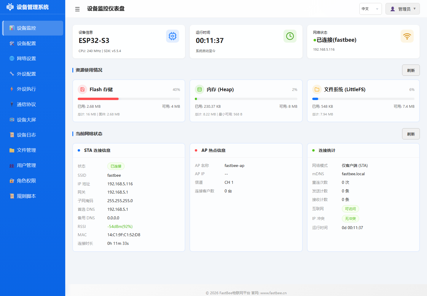
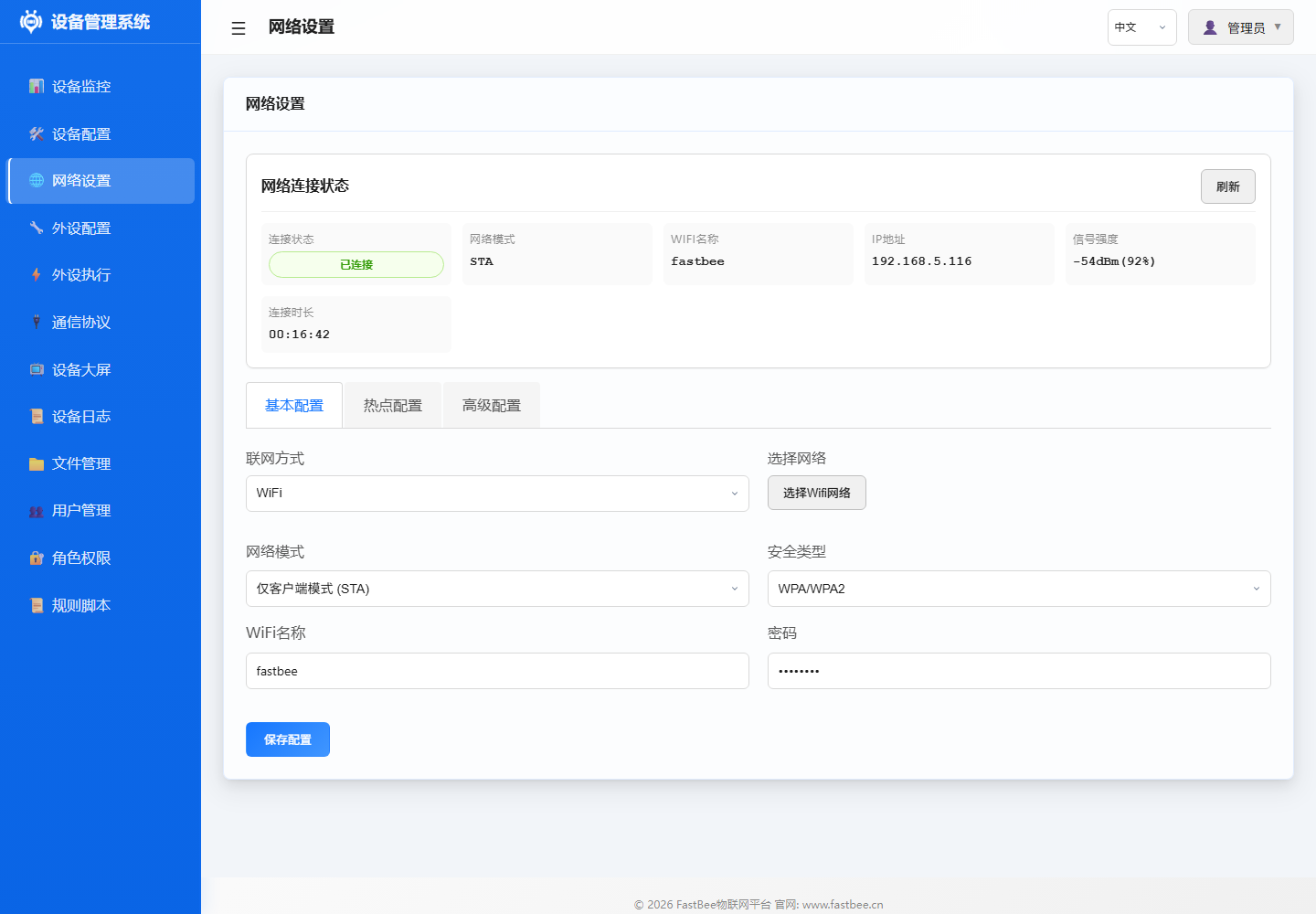
The network, peripheral, rule, protocol and system management modules in the architecture all map to the Web console. When reading the architecture diagram, you can use the following real device screenshots to correspond to runtime boundaries: the dashboard provides system status overview, the network page handles networking configuration, the peripheral page handles hardware abstraction, and the peripheral execution page handles rule orchestration.
| ID | Name | Type | Pin | Status | Actions |
|---|---|---|---|---|---|
adc | ADC Analog Conversion | ADC | 36 | Disabled | Edit / Enable / Delete |
can | CAN Bus | CAN | 4, 5 | Disabled | Edit / Enable / Delete |
i2c | I2C Bus | I2C | 17, 18 | Disabled | Edit / Enable / Delete |
jtag | JTAG Debug Interface | JTAG | 12, 13, 14, 15 | Disabled | Edit / Enable / Delete |
modbus_rtu | Modbus RTU - Industrial Device | UART | 16, 17 | Disabled | Edit / Enable / Delete |
oled_ssd1306_c3 | OLED Display - SSD1306 | LCD | 5, 6 | Disabled | Edit / Enable / Delete |
gpio_pwm | PWM Output | PWM Output | 21 | Disabled | Edit / Enable / Delete |
sdio | SD Card SDIO Interface | SDIO | 14, 15, 2, 4, 12, 13 | Disabled | Edit / Enable / Delete |
swd | SWD Debug Interface | SWD | 13, 14 | Disabled | Edit / Enable / Delete |
uart | UART Serial | UART | 16, 17 | Disabled | Edit / Enable / Delete |
| Name | Status | Trigger | Target Peripheral | Action | Stats | Actions |
|---|---|---|---|---|---|---|
| ADC Voltage Read & Report | Disabled | Timer Trigger | ADC Analog Conversion | Sensor Data Read -> ADC Analog Conversion | Trigger Count: 1 | Run Once / Edit / Enable / Delete |
| ADC Voltage Below 2.30V Close Relay | Disabled | Event Trigger | - | Set Low Level | Trigger Count: 1 | Run Once / Edit / Enable / Delete |
| ADC Voltage Above 2.50V Open Relay | Disabled | Event Trigger | - | Set High Level | Trigger Count: 1 | Run Once / Edit / Enable / Delete |
| ADC Voltage Display on Digital Tube | Disabled | Timer Trigger | - | Display Number | Trigger Count: 1 | Run Once / Edit / Enable / Delete |
| NTP Time Sync | Disabled | Platform Trigger (MQTT) | - | NTP Sync | Trigger Count: 1 | Run Once / Edit / Enable / Delete |
| OLED Temp & Humidity Display | Disabled | Timer Trigger | - | OLED Custom Display | Trigger Count: 1 | Run Once / Edit / Enable / Delete |
| OLED Custom Display - Button Trigger Device Info | Disabled | Event Trigger | - | OLED Custom Display | Trigger Count: 1 | Run Once / Edit / Enable / Delete |
| OLED Custom Display - Timer Mixed | Disabled | Timer Trigger | - | OLED Custom Display | Trigger Count: 1 | Run Once / Edit / Enable / Delete |
| OLED Custom Display - MQTT Message | Disabled | Platform Trigger (MQTT) | - | OLED Custom Display | Trigger Count: 1 | Run Once / Edit / Enable / Delete |
| OTA Upgrade | Disabled | Platform Trigger (MQTT) | - | OTA Upgrade | Trigger Count: 1 | Run Once / Edit / Enable / Delete |
The service boundary diagram maps architectural responsibilities to code modules: before adding new capabilities, first determine whether it belongs to peripheral, rule, network, protocol, system service or security boundary, then proceed to the corresponding section and directory.
Overall Architecture
FastBee-Arduino adopts a layered architecture design with clear separation of responsibilities from hardware to application layer, reducing module coupling.
System Positioning & Stability Baseline
FastBee-Arduino is positioned as an embedded IoT software system for device access, data collection, protocol reporting, remote control and field maintenance. Lite, Standard and Full editions allow feature trimming, but basic stability capabilities must remain consistent: the system can boot, configuration can be recovered, network errors can reconnect, platform connection errors can recover, insufficient memory can trigger degradation protection, and faults can be located through logs or error codes. Full edition feature boundaries and resource limits: Edition Comparison Guide.
Long-Term Operation Design Principles
- Features can be trimmed, but recovery chains cannot: boot, provisioning, network reconnection, config protection, health monitoring and logging must be preserved across all three editions.
- Full edition carries more capabilities and must rely on PSRAM, memory gating and interface degradation strategies; if
psramTotalis 0 at runtime, it should be treated as a hardware or build tier anomaly. - Lite edition prioritizes low-resource stable operation and does not enable heavy features like OTA, file management, user roles, RuleScript by default.
- Standard edition is for regular business deployment and should cover Modbus, Command Script, RuleScript, I2C/RFID/IR and other common field capabilities; multi-networking like Ethernet and 4G defaults to Full or custom builds.
- All editions must pass build, smoke and long-term stability verification before release; Full edition must also cover OTA, remote configuration, log/file and permission-related interfaces.
Stability Baseline
The design goal of error recovery is to let the device automatically return to a working state in unattended scenarios. Network, MQTT, config files, peripheral initialization and OTA should all provide clear error codes on failure and avoid infinite restarts or high-frequency Flash writes.
Module Responsibilities
Core Framework Layer
The core framework contains FastBeeFramework (main framework), PeriphExecManager (rule engine) and CommandBus (command bus). Detailed class and method descriptions: Core Framework.
- FastBeeFramework: Singleton pattern, system initialization and lifecycle management, sequentially loads config -> peripherals -> network -> protocol -> rules -> health monitor
- PeriphExecManager: 4 trigger types (platform/timer/event/poll) + 27 action types, async worker pool scheduling, config persisted to LittleFS
- CommandBus: Command script parsing and execution, supports PERIPH/DELAY/LOOP three command types
Peripheral Management Layer
Peripheral management is handled by PeripheralManager, including pin assignment, conflict detection, hardware initialization and driver registration. Supports 25+ peripheral types. Detailed interface descriptions for sensor drivers, display drivers and digital tube drivers: Core Framework.
- PeripheralManager: Peripheral CRUD, pin assignment and conflict detection, hardware initialization, ISR interrupt queue dispatch
- SensorDriver: DHT/DS18B20/HC-SR04/SHT31/AHT20/BH1750/BMP280/MPU6050 etc.
- LCDManager: SSD1306/SH1106 OLED
- SevenSegmentDriver: TM1637 digital tube
Network Communication Layer
The network layer manages multiple networking options through NetworkManager; upper-layer protocols do not need to be aware of the underlying network type. WiFiManager handles AP/STA dual mode, reconnection and mDNS; WebConfigManager provides RESTful API and static asset services based on ESPAsyncWebServer.
- NetworkManager: WiFi/Ethernet(W5500)/4G(EC801E) adaptation, unified interface through Arduino Client abstraction layer
- WiFiManager: AP provisioning (
fastbee-ap), STA connection, dual-mode concurrency, exponential backoff reconnect, mDNS - WebConfigManager: Async HTTP server, routes cover static assets, device/peripheral/execution/protocol/system APIs
Protocol Processing Layer
The protocol layer is managed by ProtocolManager, supporting MQTT and Modbus RTU as the two main protocols. Detailed topic formats and register operations: Core Framework and Protocol Docs.
- ProtocolManager: Protocol config loading, instance initialization, data reporting dispatch, command delivery handling
- MQTTClient: TLS/non-TLS connection, custom topic prefix, LWT (Last Will and Testament), auto-reconnect with exponential backoff
- ModbusHandler: UART multi-port, auto slave scanning, register batch polling, function codes 01-06/15/16
System Management Layer
System management covers config storage, health monitoring, logging and authentication. Detailed API and threshold descriptions: Core Framework.
- ConfigStorage: JSON config read/write, LittleFS persistence, atomic write protection, config import/export
- HealthMonitor: 5-second cycle heap memory/WiFi/MQTT status check, tiered alerts (<20KB WARN / <10KB close SSE / <5KB degrade logging), WDT 10s timeout
- LoggerSystem: ERROR/WARN/INFO/DEBUG four-level logging
- AuthManager: Session/Cookie authentication, single admin mode, password encryption
Data Flows
Sensor Data Collection Flow
Timer Trigger -> PeriphExecManager
              -> Read Sensor (SensorDriver)
              -> Write Local Cache (sensor_cache)
              -> Generate Data Event (ds:<id>_<field>)
              -> Trigger Linked Rule (EventTrigger)
              -> Execute Action (GPIO/Display/Report)
-> MQTT Report (MQTTClient)Example: Temperature threshold alarm
- Timer trigger fires every 10 seconds
- PeriphExecManager calls DHT11 to read temperature
- Temperature value written to local cache, generates event
ds:dht_01_temperature - Event trigger evaluates condition (temperature > 30 deg C)
- Condition met, execute action: set relay pin high
- Execution result reported to cloud platform via MQTT
Web Configuration Flow
Browser Request -> WebConfigManager (ESPAsyncWebServer)
                -> Route Matching (RouteHandler)
                -> Auth Verification (AuthManager)
                -> ConfigStorage Read/Write LittleFS
                -> Return JSON Response
-> Frontend Renders PageExample: Add a peripheral
- Frontend POST
/api/peripherals - PeripheralRouteHandler receives request
- AuthManager verifies permissions
- PeripheralManager validates pins, initializes hardware
- ConfigStorage writes to peripherals.json
- Returns 200 OK, frontend refreshes list
MQTT Message Processing Flow
MQTT Message Arrives -> MQTTClient.onMessage()
                     -> ProtocolManager Parses Topic
                     -> PeriphExecManager Platform Trigger
                     -> Condition Evaluation (evaluateCondition)
                     -> Execute Action (dispatchAction)
-> Report Response (publish)Example: Platform remote control
- Cloud platform publishes message to
fastbee/device01/command - MQTTClient receives message, calls back ProtocolManager
- PeriphExecManager matches platform trigger
- Evaluates condition (e.g., data value match)
- Executes action (e.g., open relay)
- Execution result reported to
fastbee/device01/event
Key Design Patterns
Singleton Pattern
Use Case: Globally unique managers
Implementation:
class FastBeeFramework {
public:
    static FastBeeFramework* getInstance() {
        static FastBeeFramework instance;
        return &instance;
    }
private:
    FastBeeFramework() {}
};Usage:
- FastBeeFramework::getInstance()
- PeriphExecManager::getInstance()
- ConfigStorage::getInstance()
- HealthMonitor::getInstance()
Observer Pattern
Use Case: Event listening and dispatch
Implementation:
- Sensor data event listeners (
sensor_cache) - MQTT message subscription dispatch (topic filter)
- System event broadcast (WiFi connection/MQTT status)
Data Event Format:
ds:<peripheral_id>_<field_name>
Example: ds:dht_01_temperature
         ds:bh1750_01_illuminance
Strategy Pattern
Use Case: Multiple interchangeable implementations
Implementation:
Multi-networking adaptation (WiFi/Ethernet/4G)
- Unified interface:
NetworkAdapter - Different implementations:
WiFiManager,EthernetAdapter,CellularAdapter
- Unified interface:
Multi-sensor driver strategy (DHT/DS18B20/I2C etc.)
- Unified interface:
SensorDriver - Different implementations: sensor-specific drivers
- Unified interface:
Multi-protocol handling strategy (MQTT/Modbus/TCP/HTTP)
- Unified interface:
ProtocolHandler - Different implementations:
MQTTClient,ModbusHandler,TCPHandler,HTTPClientWrapper
- Unified interface:
Command Pattern
Use Case: Action encapsulation and execution
Implementation:
- PeriphExec action execution (27 action types)
- CommandBus command dispatch (script engine)
- RuleScript script execution (Standard / Full; Lite disabled by default)
Action Execution Flow:
Parse actionType -> Match Execution Strategy -> Call Corresponding Method -> Return ResultMemory Management Strategy
Memory Gating MEMGUARD
Goal: Prevent memory exhaustion from causing system crash
Strategy:
- Periodic heap memory check (every 5 seconds)
- Service degradation based on thresholds:
- < 20KB: WARN log
- < 10KB: Close SSE connections (free ~8KB)
- < 5KB: Reduce log level, minimize string allocation
- No auto-recovery (avoid frequent oscillation), requires external intervention
Zero-Copy Optimization
Goal: Reduce memory copying and temporary objects
Implementation:
- Web response streaming (write directly to client, no buffering)
- JSON config loaded on demand (no full cache)
- Gzip compressed assets used directly (no decompression)
- Avoid
std::make_shared<File>(fails under high fragmentation)
Static Pooling
Goal: Avoid runtime dynamic allocation, reduce heap fragmentation
Implementation:
- Worker pool pre-created (3 async tasks)
- Task stack fixed size (4KB/8KB)
- Allocated at startup, no expansion during runtime
- Minimum heap gating (30KB required to allow async tasks)
Compile-Time Optimization
Memory Release:
- Disable Bluetooth controller (~30KB):
esp_bt_controller_mem_release() - Disable unused features (OTA/logging)
Stack Optimization:
- Enlarge loopTask stack to 24KB (default 8KB)
- Prevent deep call chain stack overflow
Related Documentation
- Core Framework - Main components and key class details
- Peripheral Execution Flow - Complete rule engine business logic
- Build Configuration - PlatformIO environments, feature flags and source filtering
- Resource Usage & Feature Trimming - RAM/Flash budget and trimming strategy
- TCP Connection Budget - Web/API concurrent connection limits and optimization
- Quick Start - Complete first configuration in 5 steps
- Development Guide - Environment setup and coding standards