
Quick Start
Quick Start
This guide is for first-time FastBee-Arduino users, following the shortest path from online firmware flashing to creating linked rules. No coding or local build required - just 5 steps to turn ESP32 into a controllable IoT terminal.
Prerequisites
Required Tools
- Chrome or Edge browser
- ESP32 series DevKit (ESP32/ESP32-S3/ESP32-C3/ESP32-C6)
- USB data cable (data transfer capable)
- Online Flashing Tool: esp32-flasher.md
Optional Tools
- DHT11 temperature/humidity sensor
- Relay module
- Breadboard and jumper wires
Step 1: Flash Firmware Online
Open the Online Flashing Tool. Regular users can directly use the built-in merged firmware; no need to install VSCode, PlatformIO or manually upload Web file system.
1.1 Select Firmware
- ESP32 standard DevKit: prefer
FastBee ESP32 Merged Firmware F4R0 - ESP32-C3 / ESP32-C6 DevKit: select the
F4R0firmware matching your chip model from the dropdown - ESP32-S3 DevKit: select
F8R0,F8R4orF16R8based on module resources; check module silkscreen or DevKit specs if unsure
Full firmware version, Flash/PSRAM reference and browser flashing notes: Online Flashing Tool.
1.2 Connect and Flash
- Connect the DevKit with a USB data cable
- In the online flashing tool, click Select Serial Port and choose the board port
- Keep Firmware Source as Built-in File, select the merged firmware matching your board, keep flash address at
0x0 - Click Flash, wait for progress to complete and auto-reset
Merged firmware already includes bootloader, partition table, application firmware and Web file system. No need to flash other files separately.
Default peripherals and execution rules are safe templates: after flashing, GPIO, UART or display will not be driven automatically. Before first wiring, confirm pins, power supply and peripheral IDs, then enable corresponding peripherals and rules in the Web console.
Step 2: Initial Configuration
2.1 Connect to Device
- On first boot or when WiFi is not configured, device auto-enters AP mode
- Connect to device AP hotspot:
fastbee-ap, password:admin123 - Browser access:
http://192.168.4.1orhttp://fastbee.local - Login with default credentials:
- Username:
admin - Password:
admin123
- Username:
After login, you should see network status, IP address and resource usage in the dashboard. If pages load but data is empty, wait for the device to finish booting, or refresh and re-login.
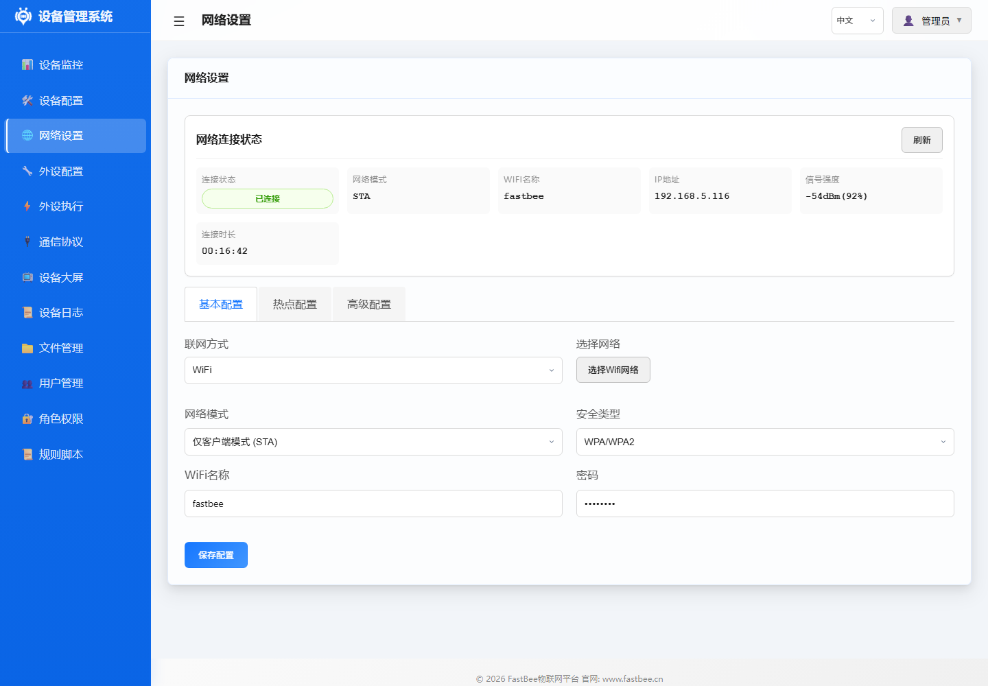
2.2 Configure Network
- Go to Network Configuration page
- Select networking method:
- WiFi STA (all editions): Enter your WiFi SSID and password
- Ethernet (Full/custom builds): Confirm W5500 SPI pins
- 4G (Full/custom builds): Enter APN and serial pins
- Click Save, device reboots and connects to network
- After connection, access via router-assigned IP or
http://fastbee.local
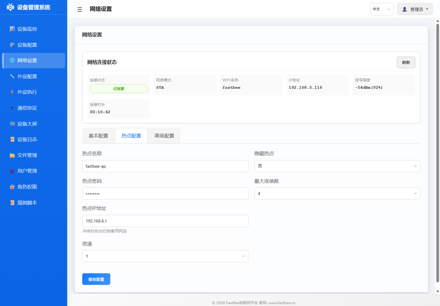
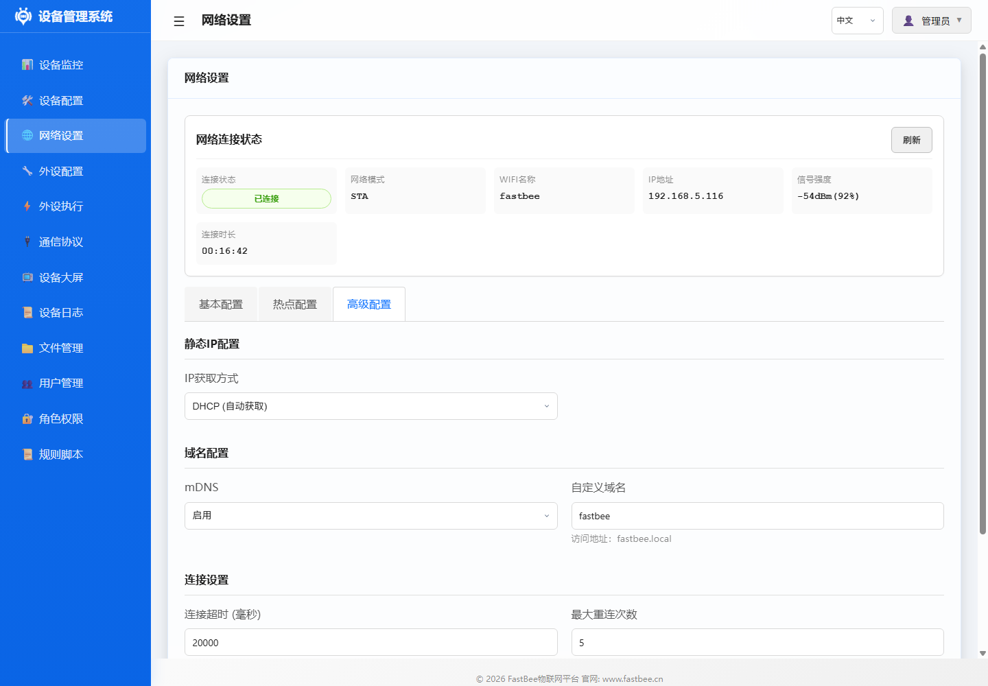
The network page top shows current connection status, SSID, IP address and signal strength; tabs below are for STA basic config, AP hotspot config and advanced config like static IP/mDNS.
Lite only retains WiFi/mDNS/MQTT and basic peripheral capabilities by default. For Modbus, use
esp32-F4R0oresp32s3-F8R0Standard edition; for Ethernet/4G, use Full firmware or custom builds.
Step 3: Configure Peripherals
3.1 Add DHT11 Temperature/Humidity Sensor
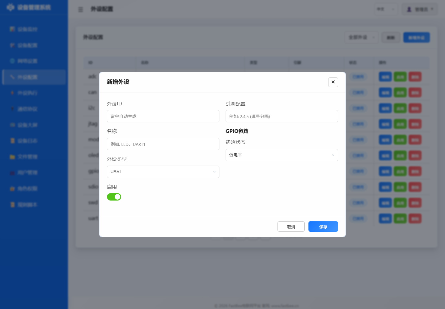
- Go to Peripheral Configuration page
- Click Add Peripheral
- Fill in configuration:
- Peripheral ID:
dht_01 - Name:
DHT11 Temp & Humidity - Type:
SENSOR(type: 38) - Pin:
13(modify based on actual wiring) - Enable: Keep disabled first, enable after confirming pins
- Peripheral ID:
- Click Save
The peripheral configuration page lists existing peripherals and enable status. When adding new peripherals, fill in peripheral ID, name, type and pins first, then enable after confirming wiring.
| ID | Name | Type | Pin | Status | Actions |
|---|---|---|---|---|---|
adc | ADC Analog Conversion | ADC | 36 | Disabled | Edit / Enable / Delete |
can | CAN Bus | CAN | 4, 5 | Disabled | Edit / Enable / Delete |
i2c | I2C Bus | I2C | 17, 18 | Disabled | Edit / Enable / Delete |
jtag | JTAG Debug Interface | JTAG | 12, 13, 14, 15 | Disabled | Edit / Enable / Delete |
modbus_rtu | Modbus RTU - Industrial Device | UART | 16, 17 | Disabled | Edit / Enable / Delete |
oled_ssd1306_c3 | OLED Display - SSD1306 | LCD | 5, 6 | Disabled | Edit / Enable / Delete |
gpio_pwm | PWM Output | PWM Output | 21 | Disabled | Edit / Enable / Delete |
sdio | SD Card SDIO Interface | SDIO | 14, 15, 2, 4, 12, 13 | Disabled | Edit / Enable / Delete |
swd | SWD Debug Interface | SWD | 13, 14 | Disabled | Edit / Enable / Delete |
uart | UART Serial | UART | 16, 17 | Disabled | Edit / Enable / Delete |
JSON Configuration Example:
{
  "id": "dht_01",
  "name": "DHT11 Temp & Humidity",
  "type": 38,
  "enabled": false,
  "pinCount": 1,
  "pins": [13, 255, 255, 255, 255, 255, 255, 255],
  "params": {}
}
3.2 Add Relay
- Click Add Peripheral
- Fill in configuration:
- Peripheral ID:
relay_01 - Name:
High Temp Relay - Type:
GPIO_DIGITAL_OUTPUT(type: 12) - Pin:
25(modify based on actual wiring) - Initial State:
0(low level)
- Peripheral ID:
- Click Save
JSON Configuration Example:
{
  "id": "relay_01",
  "name": "High Temp Relay",
  "type": 12,
  "enabled": false,
  "pinCount": 1,
  "pins": [25, 255, 255, 255, 255, 255, 255, 255],
  "params": {
    "initialState": 0,
    "pwmChannel": 0,
    "pwmFrequency": 1000,
    "pwmResolution": 8,
    "defaultDuty": 0
  }
}
3.3 Enable Peripherals
- Confirm pin wiring is correct
- Check Enable in the peripheral list
- Click Save All
- Serial log should show peripheral initialization success
Step 4: Create Linked Rules
4.1 Temperature Threshold Alarm Rule
- Go to Peripheral Execution page
- Click Add Rule
- Fill in basic info:
- Rule ID:
exec_temp_relay - Name:
Open Relay When Temp > 30 - Enable: Keep disabled first, enable after testing
- Rule ID:
4.2 Configure Trigger
- Add trigger:
- Trigger Type:
Timer Trigger(triggerType: 1) - Trigger Peripheral:
dht_01 - Timer Mode:
Periodic - Interval:
10(read every 10 seconds)
- Trigger Type:
- Click Save Trigger
4.3 Configure Actions
Action 1: Read Temperature Sensor
- Add action:
- Target Peripheral:
dht_01 - Action Type:
Sensor Read(actionType: 19) - Action Parameters:
{
  "periphId": "dht_01",
  "sensorCategory": "dht11",
  "dataField": "temperature",
  "sensorLabel": "Temperature",
  "unit": "°C",
  "decimalPlaces": 1
}
- Target Peripheral:
- Click Save Action
Action 2: Open Relay
- Add action:
- Target Peripheral:
relay_01 - Action Type:
GPIO High(actionType: 0) - Sync Delay:
100ms
- Target Peripheral:
- Click Save Action
4.4 Save and Enable Rule
- Set Report After Execution:
true - Click Save Rule
- After testing rule logic is correct, check Enable
- Click Save All
The peripheral execution page shows rule status, trigger methods, target peripherals and actions. For newly imported or created rules, keep disabled first - click "Run Once" or edit to check parameters before enabling.
| Name | Status | Trigger | Target Peripheral | Action | Stats | Actions |
|---|---|---|---|---|---|---|
| ADC Voltage Read & Report | Disabled | Timer Trigger | ADC Analog Conversion | Sensor Data Read -> ADC Analog Conversion | Trigger Count: 1 | Run Once / Edit / Enable / Delete |
| ADC Voltage Below 2.30V Close Relay | Disabled | Event Trigger | - | Set Low Level | Trigger Count: 1 | Run Once / Edit / Enable / Delete |
| ADC Voltage Above 2.50V Open Relay | Disabled | Event Trigger | - | Set High Level | Trigger Count: 1 | Run Once / Edit / Enable / Delete |
| ADC Voltage Display on Digital Tube | Disabled | Timer Trigger | - | Display Number | Trigger Count: 1 | Run Once / Edit / Enable / Delete |
| NTP Time Sync | Disabled | Platform Trigger (MQTT) | - | NTP Sync | Trigger Count: 1 | Run Once / Edit / Enable / Delete |
| OLED Temp & Humidity Display | Disabled | Timer Trigger | - | OLED Custom Display | Trigger Count: 1 | Run Once / Edit / Enable / Delete |
| OLED Custom Display - Button Trigger Device Info | Disabled | Event Trigger | - | OLED Custom Display | Trigger Count: 1 | Run Once / Edit / Enable / Delete |
| OLED Custom Display - Timer Mixed | Disabled | Timer Trigger | - | OLED Custom Display | Trigger Count: 1 | Run Once / Edit / Enable / Delete |
| OLED Custom Display - MQTT Message | Disabled | Platform Trigger (MQTT) | - | OLED Custom Display | Trigger Count: 1 | Run Once / Edit / Enable / Delete |
| OTA Upgrade | Disabled | Platform Trigger (MQTT) | - | OTA Upgrade | Trigger Count: 1 | Run Once / Edit / Enable / Delete |
The rule editing window expands different fields based on trigger and action types. Before saving, focus on verifying target peripheral, comparison value, action parameters and "Enable" status.
| Check Item | Pre-Enable Confirmation | Risk Note |
|---|---|---|
| Basic Info | Name is recognizable, ID is unique, save as disabled first, add field notes | Make the rule an auditable object first, then verify individually |
| Trigger | Source is clear, conditions are reproducible, polling interval is reasonable, event name is accurate | Do not mix up platform/timer/event/poll when troubleshooting |
| Action | Target peripheral exists, actionType is correct, actionValue is valid, strong actions confirmed | Manually run relay, motor, register write once first |
| Result & Reporting | Logs are traceable, reporting fields are correct, failures have responses, screenshots for evidence | Check not only device action but also what the platform receives |
| Rollback | Can be disabled, backup exists, recovery entry is known, on-site power-off point is clear | Dangerous actions must retain physical emergency stop |
During quick start, only enable one simple rule. After confirming relay, sensor reading and logs are all normal, continue expanding to platform triggers, event triggers or multi-action linked rules.
Complete JSON Configuration:
{
  "id": "exec_temp_relay",
  "name": "Open Relay When Temp > 30",
  "enabled": false,
  "execMode": 0,
  "triggers": [
    {
      "triggerType": 1,
      "triggerPeriphId": "dht_01",
      "timerMode": 0,
      "intervalSec": 10,
      "timePoint": "",
      "eventId": "",
      "operatorType": 0,
      "compareValue": "",
      "pollResponseTimeout": 1000,
      "pollMaxRetries": 2,
      "pollInterPollDelay": 100
    }
  ],
  "actions": [
    {
      "targetPeriphId": "dht_01",
      "actionType": 19,
      "actionValue": "{\"periphId\":\"dht_01\",\"sensorCategory\":\"dht11\",\"dataField\":\"temperature\",\"sensorLabel\":\"Temperature\",\"unit\":\"°C\",\"decimalPlaces\":1}",
      "useReceivedValue": false,
      "syncDelayMs": 0,
      "execMode": 0
    },
    {
      "targetPeriphId": "relay_01",
      "actionType": 0,
      "actionValue": "",
      "useReceivedValue": false,
      "syncDelayMs": 100,
      "execMode": 0
    }
  ],
  "protocolType": 0,
  "scriptContent": "",
  "reportAfterExec": true
}
Step 5: Configure Cloud Connection (Optional)
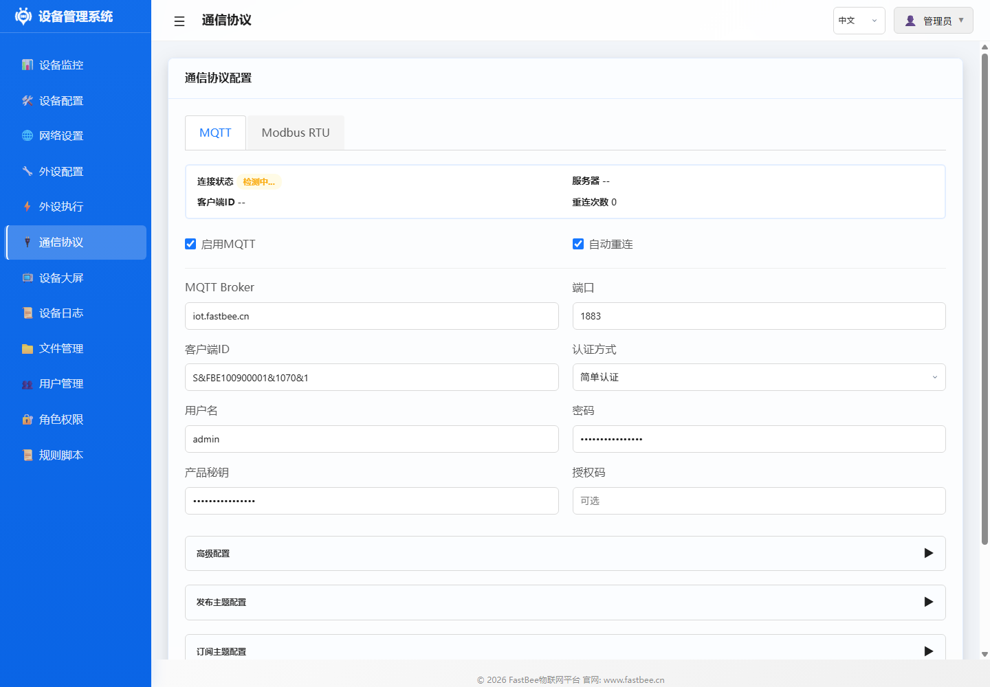
5.1 MQTT Configuration
- Go to Communication Protocol page
- Select MQTT tab
- Fill in configuration:
- Server Address:
mqtt.your-server.com - Port:
1883(non-encrypted) or8883(TLS) - Client ID: Auto-generated or manually entered
- Username/Password: Based on server requirements
- Topic Prefix:
fastbee/device01
- Server Address:
- Click Save & Connect
- Check connection status, confirm success
The communication protocol page contains MQTT and Modbus RTU tabs. MQTT is for cloud platform connection; Modbus RTU is for RS485 slave acquisition and control.
| Area | Field | Example Value / Status |
|---|---|---|
| Status Overview | Risk Level | Low |
| Status Overview | Enabled Tasks | 0 |
| Status Overview | Timeout Rate | 0% |
| Status Overview | Total Poll / Success / Fail / Timeout | 0 / 0 / 0 / 0 |
| Basic Config | Enable Modbus RTU | Enabled |
| Basic Config | Peripheral Config Selection | Select configured RS485/UART peripheral |
| Basic Config | Transfer Type | Passthrough (Raw HEX Frame) |
| Basic Config | DE Pin (RS485) | 14 |
| Sub-device Name | Type | Slave Address | Device Info | Enable | Actions |
|---|---|---|---|---|---|
| Temp & Humidity | Collect | 2 | FC04 @0 x2 [2 mapped] | ON | Edit / Map / Delete |
| PM25-10 | Collect | 1 | FC03 @0 x2 [2 mapped] | ON | Edit / Map / Delete |
| Weather Louver | Collect | 4 | FC03 @500 x8 [6 mapped] | ON | Edit / Map / Delete |
5.2 Verify Data Reporting
- Use MQTT client tool to subscribe to topic:
fastbee/device01/# - Wait for rule execution (every 10 seconds)
- Should receive temperature data and relay status messages
Configuration Backup
Export Configuration
- Go to Device Configuration > Advanced Configuration
- Click Export Configuration
- Select export type:
- Peripheral Config:
peripherals.json - Execution Rules:
periph_exec.json - Network Config:
network.json - All Configs: Package download
- Peripheral Config:
- Save to local backup
Import Configuration
- Click Import Configuration
- Select local JSON file
- Confirm import
- Check pin configuration, enable peripherals and rules after confirming
Important: All documentation examples default to
enabled: false. After import, check pins before enabling.
Notes
Pin Assignment Rules
- GPIO34-39: Input only, suitable for ADC/digital input
- GPIO6-11: Connected to Flash, not recommended for use
- GPIO32-39: ADC1, available when WiFi is on
- GPIO4,12-15,25-27: ADC2, not available when WiFi is on
Common Precautions
- ADC acquisition recommend using ADC1 pins (GPIO32-39)
- Relay modules may be active-low, use
ACTION_HIGH_INVERTED(actionType: 13) - DHT11 sampling interval recommend >= 2 seconds
- I2C devices share SDA/SCL but addresses must not conflict
- Export backup after completing each configuration
Next Steps
- Check Example Docs for more sensor configurations
- Read Peripheral Configuration Guide for all peripheral types
- Refer to User Manual for advanced features
- Learn Architecture Design for in-depth system understanding