
Peripheral Configuration
Peripheral Configuration
This guide consolidates all peripheral configuration content, including peripheral types, pin assignments, parameter configuration, Web configuration steps, and linkage examples.
Before choosing a module, check: Sensors and Modules List.
Table of Contents
- Peripheral Overview
- GPIO and PWM Peripherals
- Motor Control Peripherals
- Display Devices
- Temperature and Humidity Sensors
- Environmental Sensors
- Electrical Sensors
- Communication Devices
- Other Peripherals
- Pin Assignment Principles
- Web Configuration Process
- FAQ
Peripheral Overview
FastBee supports 25+ peripheral types, configured visually through the Web interface without writing code.
The peripheral page abstracts real hardware into objects that can be referenced by rules. When adding a new peripheral, first select the type, then fill in pins and parameters. It is recommended to keep new peripherals disabled on first save and enable them after confirming wiring.
| ID | Name | Type | Pins | Status | Actions |
|---|---|---|---|---|---|
adc | ADC Analog Converter | ADC | 36 | Disabled | Edit / Enable / Delete |
can | CAN Bus | CAN | 4, 5 | Disabled | Edit / Enable / Delete |
i2c | I2C Bus | I2C | 17, 18 | Disabled | Edit / Enable / Delete |
jtag | JTAG Debug Interface | JTAG | 12, 13, 14, 15 | Disabled | Edit / Enable / Delete |
modbus_rtu | Modbus RTU-Industrial Device | UART | 16, 17 | Disabled | Edit / Enable / Delete |
oled_ssd1306_c3 | OLED Display-SSD1306 | LCD | 5, 6 | Disabled | Edit / Enable / Delete |
gpio_pwm | PWM Output | PWM Output | 21 | Disabled | Edit / Enable / Delete |
sdio | SD Card SDIO Interface | SDIO | 14, 15, 2, 4, 12, 13 | Disabled | Edit / Enable / Delete |
swd | SWD Debug Interface | SWD | 13, 14 | Disabled | Edit / Enable / Delete |
uart | UART Serial Port | UART | 16, 17 | Disabled | Edit / Enable / Delete |
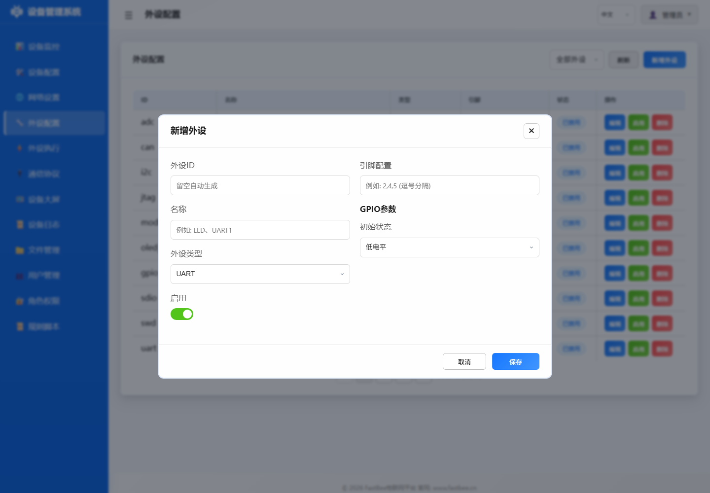
When selecting, first determine the peripheral type by hardware signal form: digital signals go to GPIO, analog signals go to ADC, bus devices go to I2C/SPI/UART, RS485 slaves go to Modbus sub-devices, and display peripherals should first pass static text tests.
Peripheral Type Quick Reference
| type value | Type Name | Description | Detailed Documentation |
|---|---|---|---|
| 11 | GPIO_DIGITAL_INPUT | Digital input | gpio-input.md |
| 12 | GPIO_DIGITAL_OUTPUT | Digital output | gpio-output.md |
| 13 | GPIO_DIGITAL_INPUT_PULLUP | Pull-up input (buttons) | gpio-input.md |
| 15 | GPIO_ANALOG_INPUT | ADC analog input | adc-input.md |
| 17 | GPIO_PWM_OUTPUT | PWM output | pwm-output.md |
| 36 | LCD | Display (SSD1306/SH1106) | oled-usage-guide.md |
| 38 | SENSOR | Sensor (DHT/DS18B20 etc.) | See individual sensor docs |
| 41 | PWM_SERVO | Servo | servo.md |
| 42 | STEPPER_MOTOR | Stepper motor | stepper-motor.md |
| 43 | ENCODER | Rotary encoder | encoder.md |
| 44 | ONE_WIRE | One-Wire (DS18B20) | sensor-ds18b20.md |
| 45 | NEO_PIXEL | WS2812B RGB LED strip | neopixel.md |
| 47 | SEVEN_SEGMENT_TM1637 | TM1637 seven-segment display | display-tm1637.md |
| 51 | MODBUS_DEVICE | Modbus slave device | modbus-device.md |
1. GPIO and PWM Peripherals
1.1 GPIO Output (type:12)
Applications: LEDs, relays, buzzers, laser sensors
Detailed Documentation: gpio-output.md
JSON Configuration:
{
  "id": "led_01",
  "name": "LED Indicator",
  "type": 12,
  "enabled": true,
  "pinCount": 1,
  "pins": [26, 255, 255, 255, 255, 255, 255, 255],
  "params": {
    "initialState": 0
  }
}
1.2 GPIO Input (type:11/13/14)
Applications: Buttons, PIR motion sensors, vibration sensors, reed switches
Detailed Documentation: gpio-input.md
1.3 ADC Input (type:15/26)
Applications: Light sensors, soil moisture, smoke, raindrop, voltage, current sensors
Detailed Documentation: adc-input.md
1.4 PWM Output (type:17)
Applications: LED dimming, motor speed control, servo control
Detailed Documentation: pwm-output.md
2. Motor Control Peripherals
2.1 Servo (type:41)
Applications: SG90, MG996R servo angle control
Detailed Documentation: servo.md
2.2 Stepper Motor (type:42)
Applications: 28BYJ-48 stepper motor precision positioning
Detailed Documentation: stepper-motor.md
3. Display Devices
3.1 OLED Display (type:36)
Applications: SSD1306, SH1106 OLED screens
Detailed Documentation: oled-usage-guide.md
Features:
- I2C interface, address 0x3C or 0x3D
- Supports text, numbers, graphics display
- Can display sensor data and system status
3.2 TM1637 Seven-Segment Display (type:47)
Applications: 4-digit 7-segment display
Detailed Documentation: display-tm1637.md
Features:
- CLK/DIO two-wire control
- Supports number, temperature, humidity display
- Can rotate display of multiple parameters
3.3 LCD1602 (type:36, placeholder)
Status: Driver to be extended
Detailed Documentation: display-lcd1602.md
4. Temperature and Humidity Sensors
4.1 DHT11/DHT22 (type:38)
Detailed Documentation: sensor-dht.md
Features:
- One-Wire communication
- DHT11: Temperature 0-50°C, Humidity 20-90%
- DHT22: Temperature -40-80°C, Humidity 0-100%
- Sampling interval ≥2 seconds
4.2 DS18B20 (type:38/44)
Detailed Documentation: sensor-ds18b20.md
Features:
- OneWire bus
- Temperature -55-125°C
- Multiple sensors can be connected in parallel (distinguished by address)
4.3 AHT20 (type:38)
Detailed Documentation: sensor-aht20.md
Features:
- I2C interface, address 0x38
- Temperature -40-85°C, Humidity 0-100%
- Lightweight I2C, available in Lite edition
4.4 SHT31 (type:38)
Detailed Documentation: sensor-sht31.md
Features:
- I2C interface, address 0x44 or 0x45
- High-precision temperature and humidity
- Lightweight I2C, available in Lite edition
5. Environmental Sensors
5.1 Ultrasonic HC-SR04 (type:38)
Detailed Documentation: sensor-ultrasonic.md
Features:
- Distance measurement 2-400cm
- Requires two pins for trigger and echo
- Sampling interval ≥100ms
5.2 BMP280 Barometric Pressure (type:38)
Detailed Documentation: sensor-bmp280.md
Features:
- I2C interface
- Temperature, barometric pressure, altitude
- Standard / Full support
5.3 MPU6050 Gyroscope (type:38)
Detailed Documentation: sensor-mpu6050.md
Features:
- I2C interface, address 0x68
- Six-axis posture (accelerometer + gyroscope)
- Standard / Full support
5.4 BH1750 Light Sensor (type:38)
Detailed Documentation: sensor-bh1750.md
Features:
- I2C interface, address 0x23 or 0x5C
- Light intensity 1-65535 lux
- Lightweight I2C, available in Lite edition
6. Electrical Sensors
6.1 Current Sensor ACS712 (type:15)
Detailed Documentation: sensor-current.md
Features:
- ADC collection
- Range 5A/20A/30A
- Requires calibration parameters
6.2 Voltage Sensor (type:15)
Detailed Documentation: sensor-voltage.md
Features:
- ADC + voltage divider circuit
- Measurement range 0-25V
- Requires divider ratio parameters
7. Communication Devices
7.1 Modbus Device (type:51)
Detailed Documentation: modbus-device.md
Features:
- RS485 interface
- Modbus RTU master
- Supports multi-slave scanning
7.2 IR Remote Control (type:38)
Detailed Documentation: ir-remote.md
Features:
- NEC/RC5 decoding
- Standard and
esp32-F8R4Full support; ESP32-S3 Full disabled by default
7.3 RFID Reader MFRC522 (type:38)
Detailed Documentation: rfid-mfrc522.md
Features:
- SPI interface
- Read RFID card UID
- Standard / Full support
8. Other Peripherals
8.1 NeoPixel WS2812B (type:45)
Detailed Documentation: neopixel.md
Features:
- Single-wire control RGB LED strip
- Supports multiple LEDs in series
8.2 Rotary Encoder (type:43)
Detailed Documentation: encoder.md
Features:
- A/B phase counting
- Supports rotation and button press
8.3 SD Card (type:37, placeholder)
Detailed Documentation: storage-sd-card.md
Status: SPI mode partially implemented, file actions to be extended; recommended to complete in Full or custom builds
8.4 Device Event (type:60)
Detailed Documentation: device-event.md
Features:
- Logical event source
- Used for rule linkage
Pin Assignment Principles
Safe Pins
- ✅ GPIO34-39: Input-only, suitable for ADC/digital input
- ✅ GPIO32-39: ADC1, available after WiFi is enabled (preferred)
- ❌ GPIO6-11: Connected to Flash, not recommended
- ❌ GPIO4,12-15,25-27: ADC2, unavailable after WiFi is enabled
- ⚠️ GPIO0: BOOT button, use with caution
- ⚠️ GPIO5: STATE indicator LED, occupied by default
I2C Devices
- SDA: GPIO21/22 (recommended)
- SCL: GPIO22/21 (recommended)
- Multiple I2C devices can share SDA/SCL, but addresses must not conflict
Web Configuration Process
Step 1: Add Peripheral
- Navigate to Web interface → Peripheral Configuration
- Click Add Peripheral
- Select peripheral type
- Fill in peripheral ID and name
- Assign pins (refer to pin assignment principles)
- Fill in parameters (e.g., I2C address, initial state, etc.)
Step 2: Enable Peripheral
- Confirm pin wiring is correct
- Check Enable
- Click Save
- Check serial log to confirm successful initialization
Step 3: Create Execution Rules
- Navigate to Peripheral Execution
- Add rule and configure trigger
- Configure actions (e.g., GPIO control, sensor read, display, etc.)
- Save and enable rule
Step 4: Configuration Backup
- Navigate to Device Configuration > Advanced Configuration
- Export peripherals.json for backup
- Save as local file
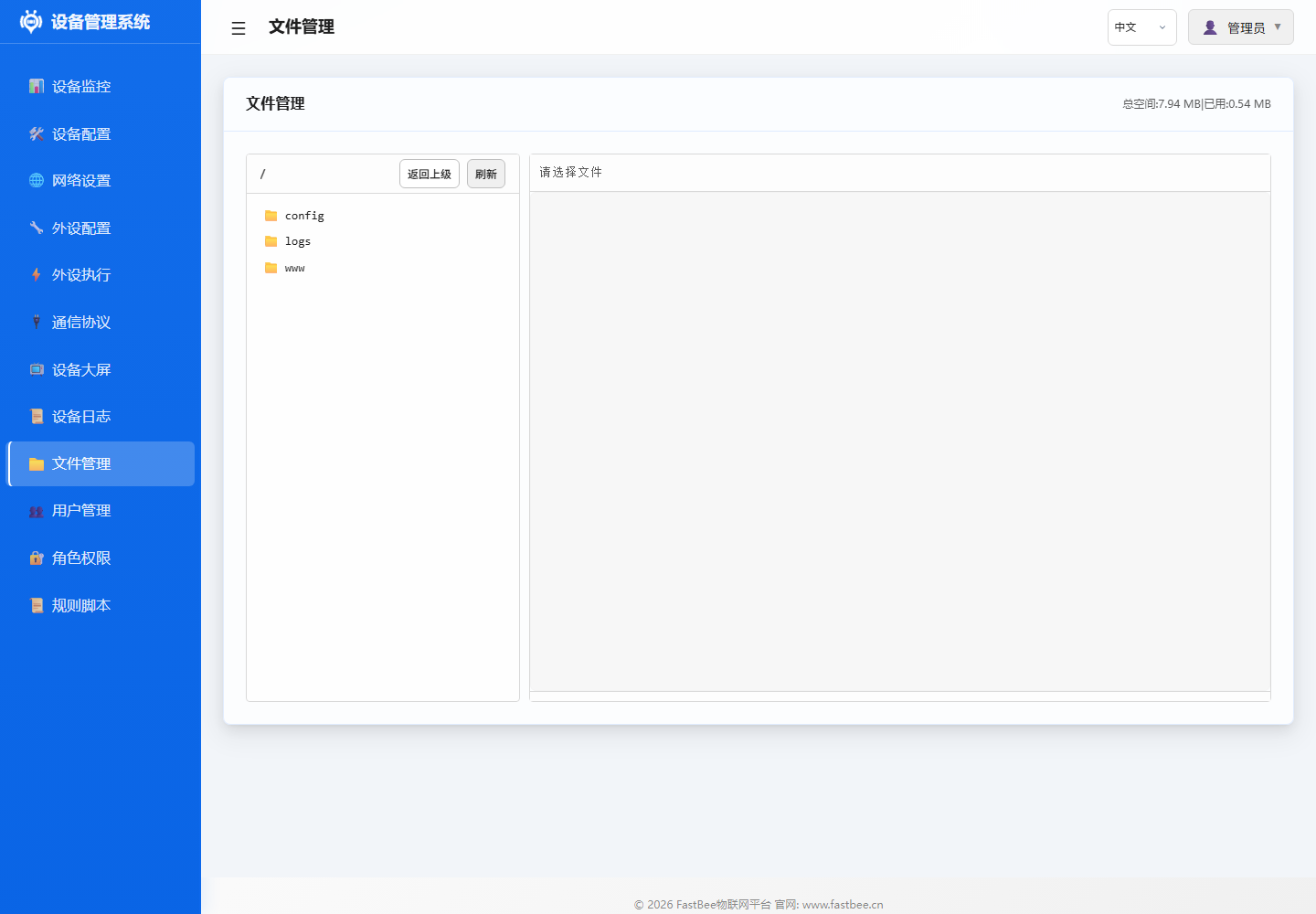
After visual configuration, it is recommended to keep a LittleFS configuration backup on the file management page for easy batch copying to same-model devices or rolling back on-site changes.
FAQ
Q1: Peripheral not responding?
- Check if the peripheral is enabled
- Check if pin configuration is correct
- Check if wiring is secure
- Check serial log to confirm initialization status
Q2: I2C device initialization failed?
- Check if SDA/SCL are reversed
- Check if I2C address is correct
- Check if pull-up resistors are present
- Confirm power supply is 3.3V
Q3: ADC values abnormal?
- Check if voltage exceeds 3.3V
- Confirm using ADC1 pins (GPIO32-39)
- Check ADC attenuation and calibration parameters
Q4: Sensor readings inaccurate?
- Check if sampling interval is too short (DHT ≥2 seconds)
- Check if sensor power supply is stable
- Confirm sensor type configuration is correct
Related Documentation
- Examples - 48 practical application examples
- Peripheral Execution Guide - Trigger and action configuration
- Complete Sensor Guide - 40+ sensor detailed specifications
- Architecture Design - System architecture and peripheral management module