
Peripheral Configuration
Peripheral Configuration
1. Overview
The peripheral management page is the hardware abstraction layer configuration center of the FastBee system, mapping physical hardware (GPIO pins, sensors, communication interfaces, etc.) to system-recognizable virtual peripheral objects through the Web interface. All configurations are stored in /config/peripherals.json.
Factory default peripheral configuration is released as a safety template, with all hardware peripherals set to enabled: false. When adding or importing peripherals for the first time, please confirm actual wiring, pin availability and power supply before enabling peripherals.
When adding a new peripheral, first select the type, then fill in name, pins and type-specific parameters. Keep "Enable" off until wiring is confirmed, then verify one by one after saving.
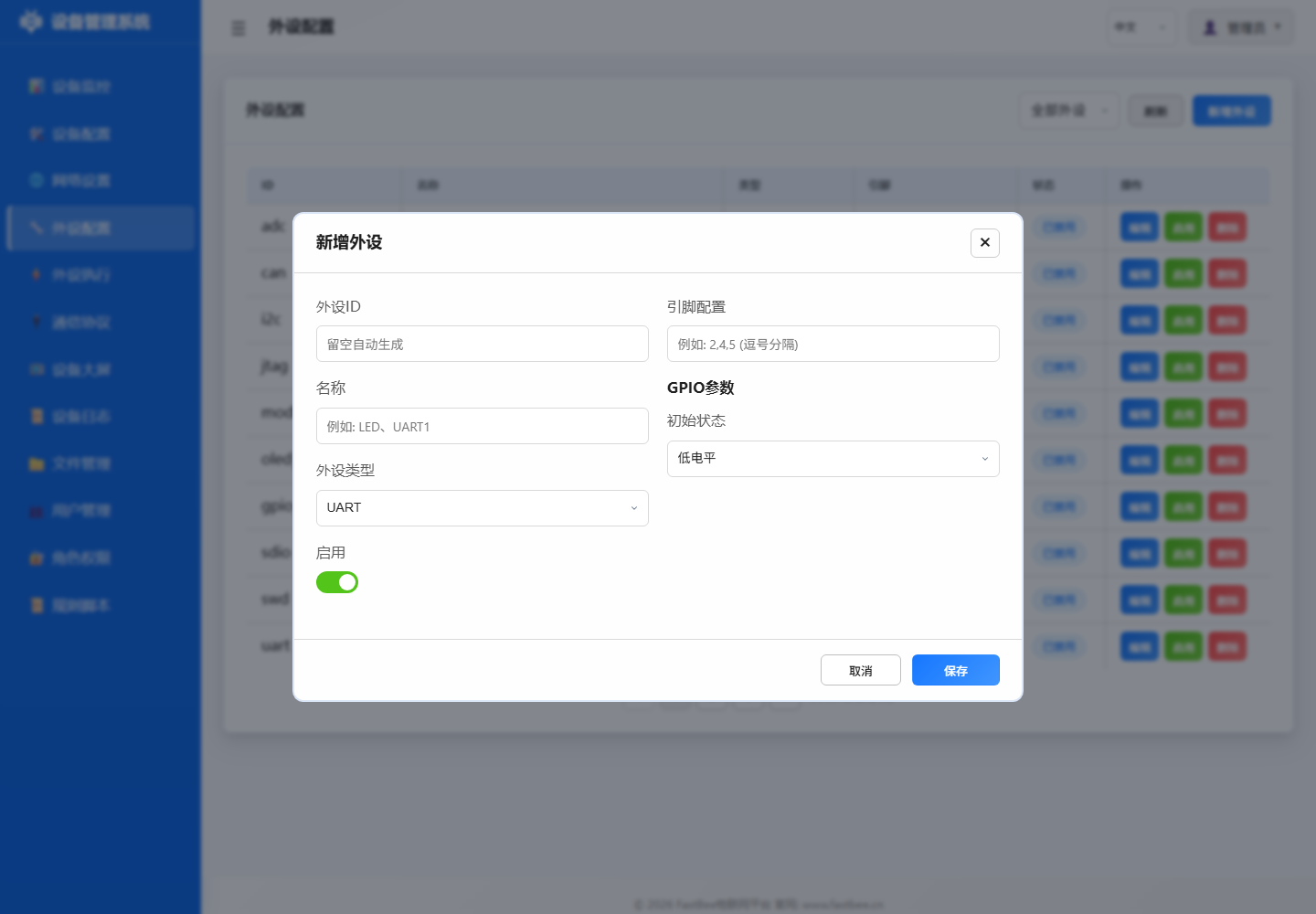
When bringing peripherals online, save as disabled first, confirm logs and individual actions are normal before enabling; peripherals that generate field actions like relays, motors, Modbus should especially be individually verified first.
Before adding a peripheral, first confirm the type category using the selection map, then fill in ID, name, pins and type parameters; this reduces mixing sensors, bus devices and virtual Modbus sub-devices.
When troubleshooting configuration issues, follow the data model order: first confirm page fields match JSON, then check save validation passed, finally confirm runtime driver initialized and whether peripheral execution, MQTT, logs reference the same peripheral ID.
| Peripheral Type | Required Fields | Key Parameters | Pre-Enable Check | Common Use |
|---|---|---|---|---|
| GPIO Output | id / type / pins[0] | initialState / invert | Load current and relay level | LED, relay, buzzer |
| GPIO Input | id / type / pins[0] | pullup / debounce | Pull-up/down and debounce time | Button, PIR, switch |
| ADC / Analog | pins[0] / category | vRef / ratio / offset | Prefer ADC1, voltage within range | Voltage, current, light, rain |
| I2C Device | SDA / SCL / address | bus / frequency / driver | Address scan and pull-up resistor | OLED, SHT31, BH1750 |
| UART / RS485 | TX / RX / baudrate | parity / stopBits / dePin | A/B wiring and direction control | Modbus RTU, serial devices |
| Display Output | type / pins / address | width / height / brightness | Power, bus, display orientation | OLED, TM1637, LCD |
| Motion Control | pins / speed / limits | angle / steps / rpm | External power and mechanical limits | Servo, stepper, motor |
| Virtual Peripheral | id / source / mapping | eventId / slaveId / register | Reference chain and version capability | DeviceEvent, Modbus sub-device |
When adding peripherals, first verify required fields and pre-enable checks against the parameter matrix, then enter specific type sections.
Core Concepts
| Concept | Description | Example |
|---|---|---|
| Peripheral ID | Unique identifier for rule reference | led1, dht_temp, relay_pump |
| Peripheral Type | Hardware type code (type value) | 12=digital output, 38=sensor |
| Pin Configuration | Physical GPIO pin array | [15], [4, 5] (I2C SDA, SCL) |
| Parameters | Type-specific config items | {initialState: 1}, {baudrate: 115200} |
| Enabled Status | Controls peripheral initialization | enabled: true occupies hardware resources |
2. Web Interface Operation Guide
2.1 Add Peripheral
Steps
Enter peripheral management page
- Click left menu Peripheral Configuration
- View peripheral list and status overview
Click Add button
- Click + Add Peripheral at top right of page
- Add peripheral dialog opens
Select peripheral type
- Select type from dropdown: GPIO Output, GPIO Input, ADC, I2C, UART, Modbus, Display, etc.
- Form dynamically adjusts based on type
Fill in peripheral information
- ID: Unique identifier (e.g.,
led_d1,sensor_temp) - Name: Display name
- Pins: GPIO pin numbers (type-specific)
- Parameters: Type-specific parameters
- ID: Unique identifier (e.g.,
Save and enable
- Click Save to add peripheral to configuration
- Toggle Enable switch to activate peripheral
Form Field Description
| Field | Type | Required | Description |
|---|---|---|---|
id | String | Yes | Unique identifier, alphanumeric and underscore |
type | Number | Yes | Peripheral type code |
name | String | No | Display name |
pins | Array | Type-specific | GPIO pin array |
params | Object | Type-specific | Type-specific parameters |
enabled | Boolean | No | Enable status, default false |
2.2 Edit Peripheral
- Find target peripheral in peripheral list
- Click Edit button
- Modify configuration in edit dialog
- Click Save to apply changes
Note: Some parameter changes require device restart to take effect.
2.3 Delete Peripheral
- Find target peripheral in peripheral list
- Click Delete button
- Confirm deletion
Warning: Deleting a peripheral referenced by execution rules will invalidate those rules.
2.4 Enable/Disable Peripheral
- Enable: Toggle enable switch, peripheral starts initializing
- Disable: Toggle disable switch, peripheral releases hardware resources
2.5 Batch Operations
- Batch Enable: Select multiple peripherals, click batch enable
- Batch Disable: Select multiple peripherals, click batch disable
- Import Configuration: Import peripherals configuration via JSON file
- Export Configuration: Export current configuration to local JSON file
3. Peripheral Type Details
3.1 GPIO Output (Digital Output)
Used to control external devices: LED, relay, buzzer, solenoid valve, etc.
Configuration Example:
{
  "id": "led_d1",
  "type": 12,
  "name": "Status LED",
  "pins": [2],
  "params": {
    "initialState": 0,
    "invert": false
  },
  "enabled": true
}
Parameter Description:
| Parameter | Type | Default | Description |
|---|---|---|---|
initialState | Number | 0 | Initial state (0=low, 1=high) |
invert | Boolean | false | Invert output logic |
3.2 GPIO Input (Digital Input)
Used to read switch status: buttons, PIR sensors, door sensors, limit switches, etc.
Configuration Example:
{
  "id": "btn_1",
  "type": 11,
  "name": "Function Button",
  "pins": [0],
  "params": {
    "pullup": true,
    "debounce": 50
  },
  "enabled": true
}
Parameter Description:
| Parameter | Type | Default | Description |
|---|---|---|---|
pullup | Boolean | true | Enable internal pull-up resistor |
debounce | Number | 50 | Debounce time (ms) |
3.3 ADC (Analog Input)
Used to read analog sensors: voltage, current, light, soil moisture, etc.
Configuration Example:
{
  "id": "adc_voltage",
  "type": 31,
  "name": "Voltage Sensor",
  "category": "voltage",
  "pins": [36],
  "params": {
    "vRef": 3.3,
    "ratio": 1.0,
    "offset": 0.0,
    "samples": 10
  },
  "enabled": true
}
Parameter Description:
| Parameter | Type | Default | Description |
|---|---|---|---|
vRef | Number | 3.3 | Reference voltage (V) |
ratio | Number | 1.0 | Scaling ratio |
offset | Number | 0.0 | Offset (raw units) |
samples | Number | 10 | Number of samples to average |
category | String | "" | Category: voltage, current, light, etc. |
Note: ESP32 ADC2 conflicts with WiFi, prefer ADC1 pins (32-39).
3.4 I2C Devices
Used for I2C bus devices: OLED displays, temperature/humidity sensors, light sensors, etc.
Configuration Example:
{
  "id": "oled_ssd1306",
  "type": 51,
  "name": "OLED Display",
  "pins": [21, 22],
  "params": {
    "address": "0x3C",
    "width": 128,
    "height": 64,
    "rotation": 0
  },
  "enabled": true
}
Parameter Description:
| Parameter | Type | Default | Description |
|---|---|---|---|
address | String | "0x3C" | I2C address (hex) |
width | Number | 128 | Display width (pixels) |
height | Number | 64 | Display height (pixels) |
rotation | Number | 0 | Display rotation (0, 90, 180, 270) |
Common I2C Addresses:
| Device | Typical Address |
|---|---|
| SSD1306 OLED | 0x3C, 0x3D |
| SHT31 Temp/Humidity | 0x44, 0x45 |
| BH1750 Light | 0x23, 0x5C |
| BMP280 Pressure | 0x76, 0x77 |
| MPU6050 Gyro | 0x68, 0x69 |
| AHT20 Temp/Humidity | 0x38 |
3.5 UART / RS485
Used for serial communication devices: Modbus RTU, GPS modules, serial displays, etc.
Configuration Example:
{
  "id": "modbus_rtu",
  "type": 61,
  "name": "Modbus RTU Master",
  "pins": [16, 17],
  "params": {
    "baudrate": 9600,
    "parity": "N",
    "stopBits": 1,
    "dePin": -1
  },
  "enabled": true
}
Parameter Description:
| Parameter | Type | Default | Description |
|---|---|---|---|
baudrate | Number | 9600 | Baud rate |
parity | String | "N" | Parity: N=none, E=even, O=odd |
stopBits | Number | 1 | Stop bits (1 or 2) |
dePin | Number | -1 | RS485 direction control pin (-1=disabled) |
RS485 Note: DE/RE pins typically tied together, high for transmit, low for receive.
3.6 Display Output
Used for display devices: OLED, LCD, LED segment displays, etc.
3.7 Motion Control
Used for motion devices: servos, stepper motors, DC motors, etc.
3.8 Virtual Peripherals
Virtual peripherals don't occupy physical pins, used for:
- DeviceEvent: Virtual peripheral triggered by device events
- Modbus Sub-device: Modbus RTU slave device mapping
4. Configuration File Format
All peripheral configurations stored in /config/peripherals.json:
{
  "version": "2.0",
  "peripherals": [
    {
      "id": "led_d1",
      "type": 12,
      "name": "Status LED",
      "pins": [2],
      "params": { "initialState": 0 },
      "enabled": true
    },
    {
      "id": "dht_temp",
      "type": 38,
      "name": "Temperature Sensor",
      "pins": [4],
      "params": { "model": "DHT11" },
      "enabled": true
    }
  ]
}
5. Version Availability
| Feature | Lite | Standard | Full |
|---|---|---|---|
| GPIO Input/Output | ✅ | ✅ | ✅ |
| ADC Analog Input | ✅ | ✅ | ✅ |
| I2C Devices | ✅ | ✅ | ✅ |
| UART/RS485 | ❌ | ✅ | ✅ |
| Modbus RTU | ❌ | ✅ | ✅ |
| Display Output | ❌ | ✅ | ✅ |
| Motion Control | ❌ | ✅ | ✅ |
| Virtual Peripherals | ❌ | ✅ | ✅ |
| Import/Export Config | ❌ | ✅ | ✅ |
6. Troubleshooting
| Issue | Possible Cause | Solution |
|---|---|---|
| Peripheral not initializing | Pin conflict or unavailable | Check pin assignment, ensure not used by other functions |
| Sensor reading abnormal | Wrong wiring or parameter error | Check wiring, verify vRef and ratio parameters |
| I2C device not responding | Address error or missing pull-up | Scan I2C bus, confirm pull-up resistors installed |
| Modbus communication failure | Baud rate or parity mismatch | Check baud rate, parity, stop bits match slave device |
| Display not showing | Address error or power issue | Confirm I2C address, check 3.3V power supply |
| Rule cannot reference peripheral | Peripheral ID error | Confirm peripheral ID matches rule reference |
| Configuration save failed | JSON format error | Check JSON syntax, ensure field types correct |
| Import configuration failed | Version incompatible | Check configuration file version, ensure compatible with current firmware |
7. Related Documentation
- Peripheral Execution Management - Automation rule configuration
- Supported Sensors and Modules - Hardware compatibility list
- Network Configuration - Network connection settings
- Protocol Configuration - MQTT and Modbus protocol settings