
Modbus RTU Configuration & Guide
Modbus RTU Configuration & Guide
For FastBee IoT Platform — ESP32 Firmware
Default adapted: Generic Chinese Modbus RTU relay module (flash-on type)
Current Version Notes
- Lite version disables Modbus RTU by default; use Standard/Full firmware or enable
FASTBEE_ENABLE_MODBUS=1in custom build. - Modbus sub-device editing, mapping and deletion are all done in the Web page.
- Modbus RTU configuration, sub-devices and mappings are saved in
/config/protocol.json. - After importing
protocol.json, it's recommended to restart the device.
Modbus debugging is mainly done in the "Communication Protocol / Modbus RTU" configuration page; when linkage is involved, go to the "Peripheral Execution" page to create polling or control rules.
Quick Reference
For the complete guide including REST API, sub-device configuration (relay/PWM/PID/motor), register mapping, polling task features, configuration examples, and troubleshooting, refer to the Chinese version.
Serial Configuration
| Config Item | Description | Default |
|---|---|---|
| Serial Port | UART1/UART2 | UART1 |
| TX Pin | Transmit pin | GPIO16 |
| RX Pin | Receive pin | GPIO17 |
| Baud Rate | Communication speed | 9600 |
| Data Bits | Number of data bits | 8 |
| Stop Bits | Number of stop bits | 1 |
| Parity | Parity method | None (0) |
Supported Function Codes
| Function Code | Description | Operation |
|---|---|---|
| 0x01 | Read Coils | Read switch values |
| 0x02 | Read Discrete Inputs | Read input status |
| 0x03 | Read Holding Registers | Read data (commonly used) |
| 0x04 | Read Input Registers | Read read-only data |
| 0x05 | Write Single Coil | Control single switch |
| 0x06 | Write Single Register | Write single value |
| 0x10 | Write Multiple Registers | Batch write |
Troubleshooting
| Issue | Possible Cause | Solution |
|---|---|---|
| Communication Timeout | Wiring error / baud rate mismatch | Check TX-RX cross wiring and baud rate |
| CRC Error | Electrical interference / line too long | Shorten line or add termination resistor (120Ω) |
| Slave No Response | Wrong address | Confirm slave address (use scan function) |
| Data Abnormal | Wrong data type / byte order | Check INT16/FLOAT32 and big/little endian settings |
| Can Read but Not Write | Wrong function code | Use 03/04 for read, 05/06/10 for write |
Sensor Status & Sub-device Management
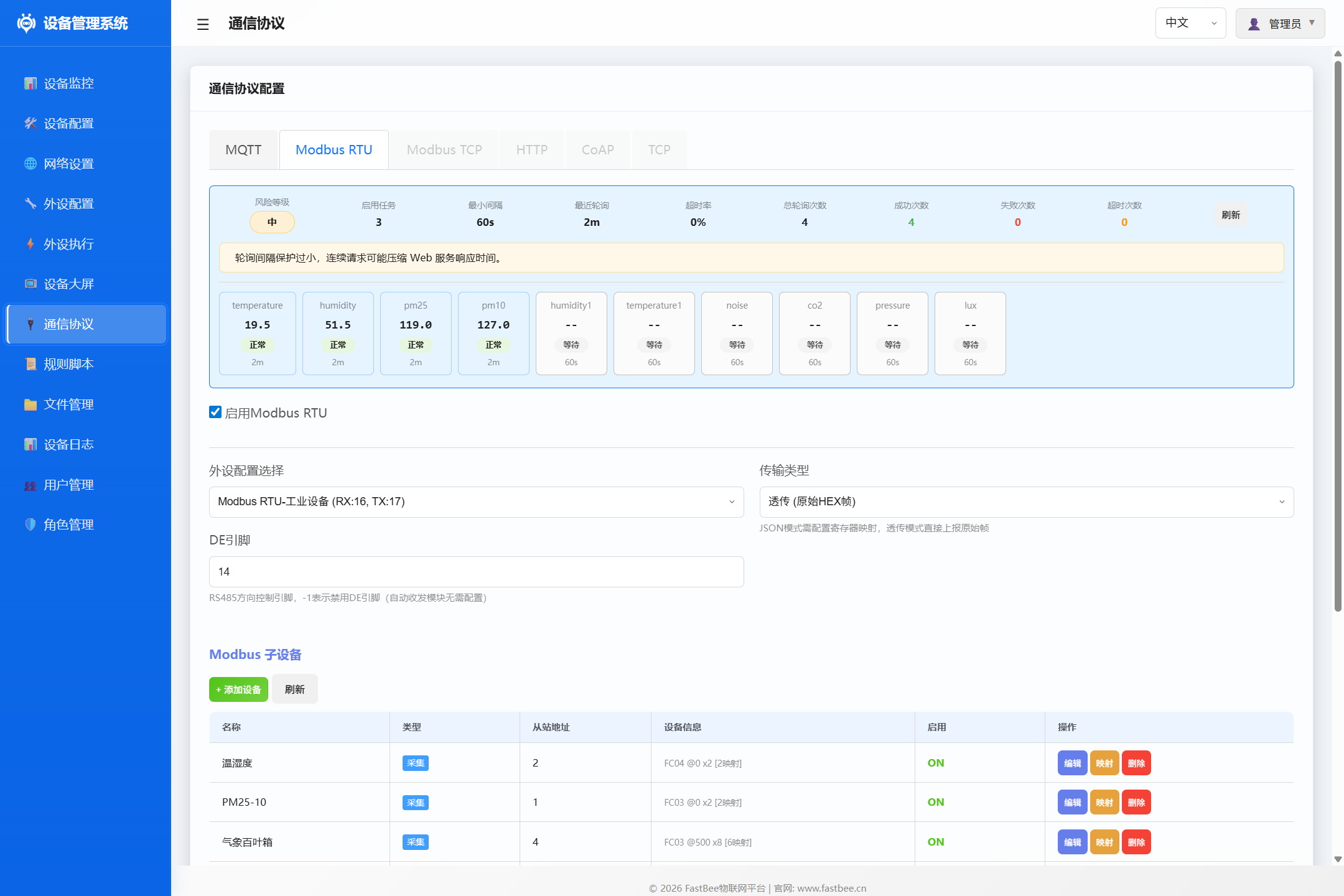
Once Modbus RTU is enabled and sub-devices are configured, the page displays real-time sensor status and a sub-device management list for monitoring data collection and managing devices.
Sensor Status Cards
The top of the page shows real-time data cards for all mapped sensors:
| Item | Description |
|---|---|
| Sensor Name | e.g. temperature, humidity, pm25 |
| Current Value | Latest collected value (after mapping and scaling) |
| Status Badge | Normal (green): data updating normally; Waiting (gray): no data collected yet |
| Update Time | Time since last data update (e.g. 2m means 2 minutes ago) |
Tip: Sensor status cards only display collection points with configured register mappings. Unmapped sensors show
--with "Waiting" status and auto-refresh once polling succeeds.
Sub-device List
The sub-device list manages all collection and control devices in one unified table, with "+ Add Device" and "Refresh" buttons.
List Columns
| Column | Description |
|---|---|
| Name | Sub-device name, e.g. "Temperature", "PM25-10", "Weather Station" |
| Type | Collection (polling task) or Control (sub-device) |
| Slave Address | Modbus slave address (1-247) |
| Device Info | Function code + start address + register count + mapping count, e.g. FC04 @0 x2 [2 mappings] |
| Enabled | Whether the sub-device is enabled (toggle switch) |
| Operations | Edit / Mapping / Delete (collection) or Edit / Control / Delete (control) |
Device Info Format
The Device Info column displays key parameters in a compact format:
FC04 @0 x2 [2 mappings]     → FC04, start address 0, 2 registers, 2 mappings
FC03 @500 x8 [6 mappings]   → FC03, start address 500, 8 registers, 6 mappings
Operations
- Edit: Open the device edit dialog to modify name, slave address, function code, start address, register count, etc.
- Mapping: Open the register mapping dialog to configure sensor name, data type, scale factor, etc. for each register
- Control: Open the device control dialog (control devices only) for relay switching, PWM adjustment, etc.
- Delete: Remove the sub-device and its associated configuration
- + Add Device: Add a new collection or control device
- Refresh: Manually refresh the sub-device list and sensor status
Related Documentation
- Modbus RTU Configuration & Guide (Chinese) — Complete guide with REST API, sub-device config, register mapping, and troubleshooting
- Modbus Sub-device Peripheral — Peripheral type configuration
- Modbus Actions — Modbus actions in Peripheral Execution rules
- Modbus Monitor Scenario — Automatic monitoring with Peripheral Execution