
Quick Start
Quick Start
This guide is for first-time users. Follow the shortest path from firmware flashing to creating an automation rule. No programming is required—just 5 steps to turn an ESP32 into a controllable IoT terminal.
Prepare Your Environment
Required Tools
- VSCode + PlatformIO IDE extension (recommended), or PlatformIO CLI
- ESP32-series dev board (ESP32 / ESP32-S3 / ESP32-C3 / ESP32-C6)
- USB data cable (must support data transfer)
Optional Tools
- DHT11 temperature/humidity sensor
- Relay module
- Breadboard and jumper wires
Step 1: Flash Firmware
1.1 Select a Firmware Edition
This project is built on Arduino-ESP32 3.x (ESP-IDF 5.1+) and supports three edition tiers:
| PIO Environment | Edition | Target Chip | Recommended Use |
|---|---|---|---|
esp32c3-F4R0 | Lite | ESP32-C3 | Low-cost node |
esp32c6-F4R0 | Lite | ESP32-C6 | WiFi 6 low-cost node |
esp32-F4R0 | Standard | ESP32 | 4 MB default production build |
esp32s3-F8R0 | Standard+OTA | ESP32-S3 | Standard edition with OTA |
esp32s3-F16R8 | Full | ESP32-S3 | OTA + multi-user + RuleScript + multilingual |
Recommendation: Start with esp32-F4R0 Standard edition. Use esp32c3-F4R0 for low-cost scenarios. Choose esp32s3-F16R8 when you need full management features.
Note: ESP32-C6 requires the pioarduino community platform. See Edition Comparison.
1.2 One-Click Build and Flash
Open a terminal and navigate to the project directory:
cd D:\project\gitee\FastBee-ArduinoUse the deployment script. It uploads the matching LittleFS Web filesystem first, then flashes the firmware:
powershell -ExecutionPolicy Bypass -File scripts\deploy.ps1 -Env esp32-F4R0 -Port COM6ESP32-S3 Standard:
powershell -ExecutionPolicy Bypass -File scripts\deploy.ps1 -Env esp32s3-F8R0 -Port COM6ESP32-S3 Full:
powershell -ExecutionPolicy Bypass -File scripts\deploy.ps1 -Env esp32s3-F16R8 -Port COM6Build only (no upload):
powershell -ExecutionPolicy Bypass -File scripts\deploy.ps1 -Env esp32s3-F16R8 -BuildOnlyThe Web filesystem and firmware version must match. Do not mix the
esp32s3-F16R8Web filesystem with theesp32-F4R0firmware.
Default peripheral and rule templates are all safe: after flashing, no GPIO, UART, or display is automatically driven. Verify pins, power, and peripheral IDs before enabling them in the Web UI.
1.3 Post-Deployment Check
After flashing and boot, run the API smoke test:
powershell -ExecutionPolicy Bypass -File scripts\smoke-test-device.ps1 -BaseUrl http://192.168.4.1 -Profile standardIf the device is already on the local network, replace the address with the actual IP:
powershell -ExecutionPolicy Bypass -File scripts\smoke-test-device.ps1 -BaseUrl http://192.168.5.116 -Profile full1.4 View Serial Logs
pio device monitor -e esp32-F4R0 -b 115200You should see chip info, memory status, and boot logs.
Step 2: Initial Configuration
2.1 Connect to the Device
- On first boot (or when WiFi is not configured), the device enters AP mode automatically.
- Connect your phone/PC WiFi to the device hotspot:
FastBee-XXXX(no password). - Open a browser to:
http://192.168.4.1orhttp://fastbee.local. - Log in with the default account:
- Username:
admin - Password:
admin123
- Username:
After login, the dashboard should show network status, IP address, and resource usage. If the page loads but data is empty, wait for the device to finish booting, then refresh and log in again.
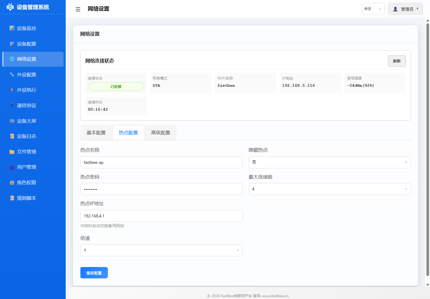
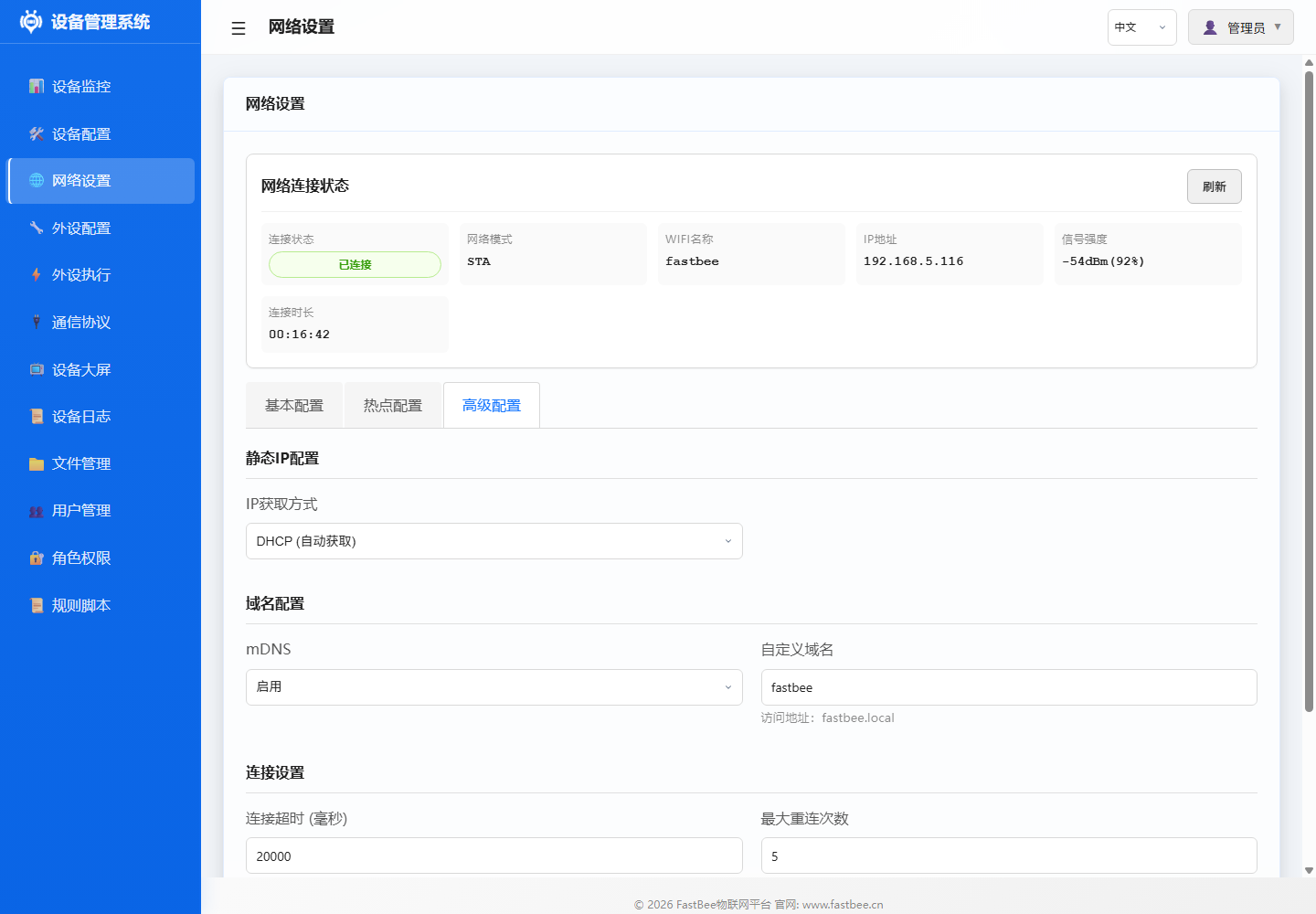
2.2 Configure Network
- Go to the Network Configuration page.
- Choose a networking method:
- WiFi STA (all editions): Enter your router SSID and password.
- Ethernet (Standard/Full): Confirm W5500 SPI pins.
- 4G (Standard/Full): Enter APN and UART pin assignments.
- LoRa (Full): Confirm UART pins and gateway online status.
- Click Save; the device reboots and connects.
- After connection, access the device via the router-assigned IP or
http://fastbee.local.
The network page shows connection status, SSID, IP address, and signal strength at the top; tabs below cover STA config, AP hotspot config, and advanced settings (static IP, mDNS).
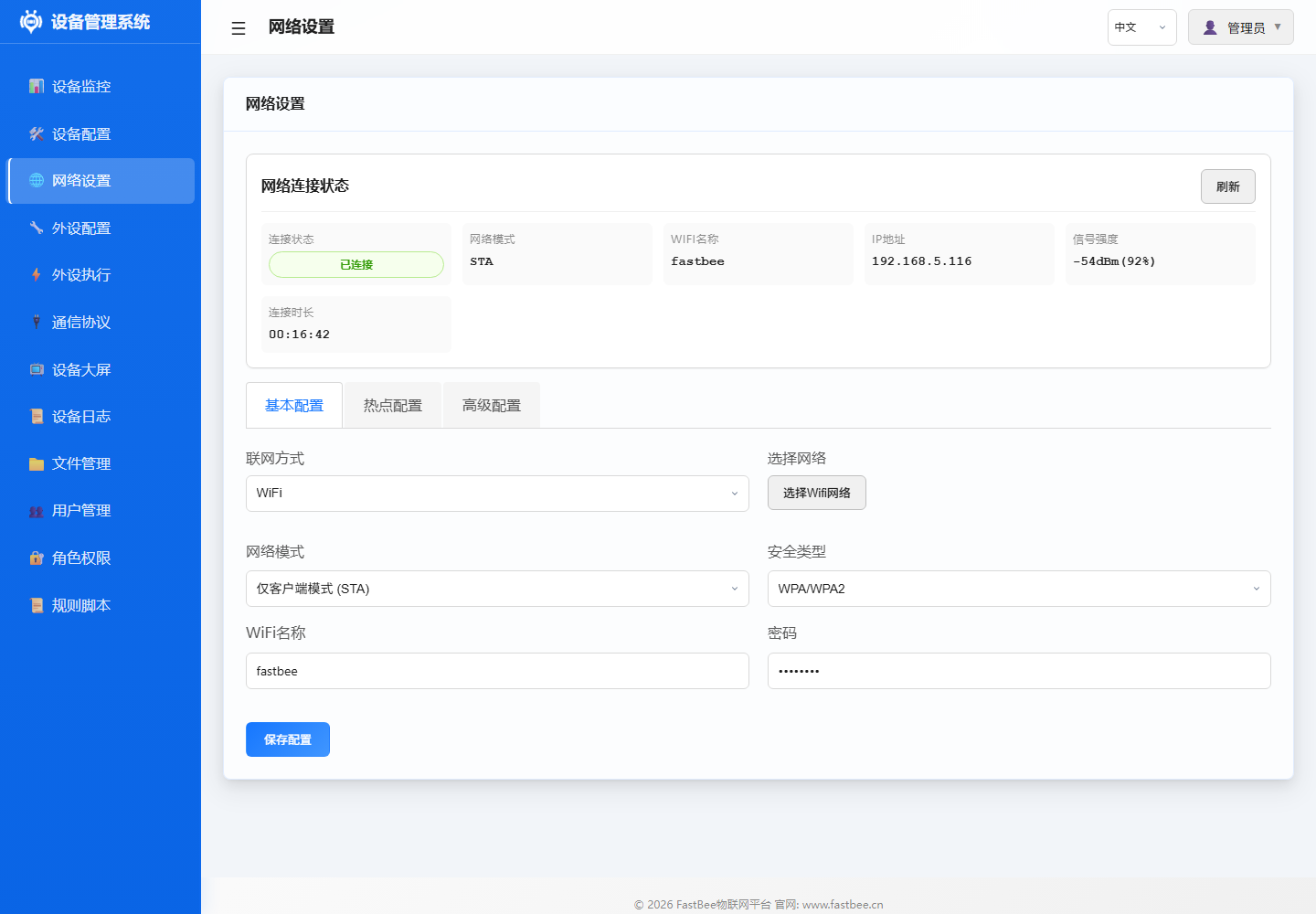
Lite edition only provides WiFi/mDNS/MQTT and basic peripherals. For Ethernet, 4G, or Modbus, use
esp32-F4R0oresp32s3-F8R0Standard edition.
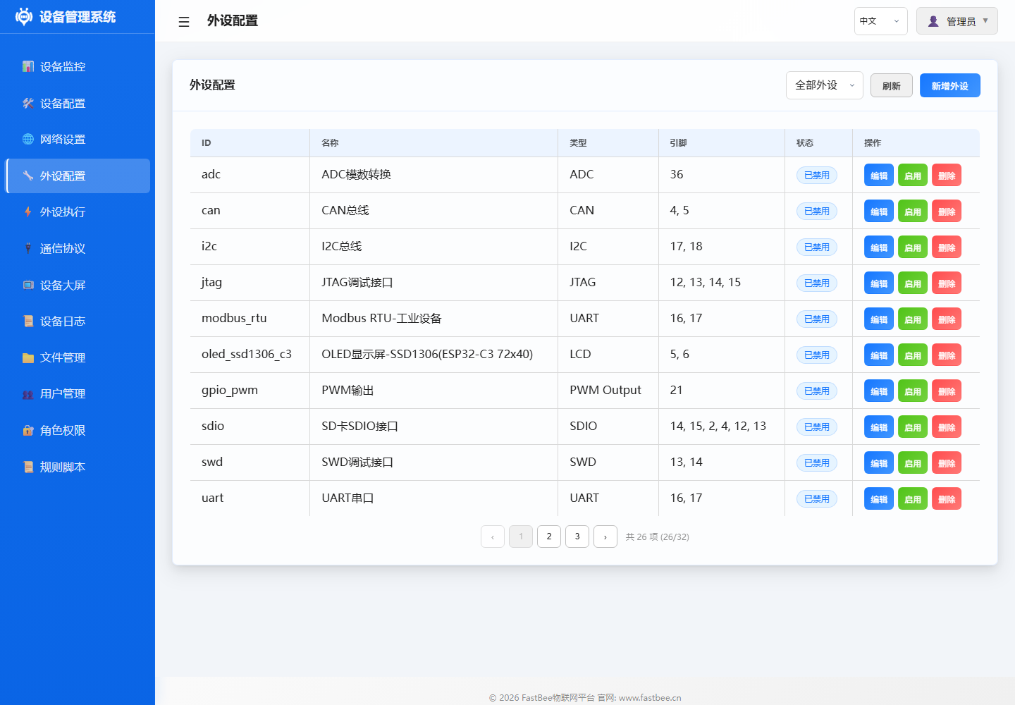
Step 3: Configure Peripherals
3.1 Add a DHT11 Temperature/Humidity Sensor
- Go to the Peripheral Configuration page.
- Click Add Peripheral.
- Fill in:
- Peripheral ID:
dht_01 - Name:
DHT11 Temp/Humidity - Type:
SENSOR(type: 38) - Pin:
13(adjust to your wiring) - Enabled: Keep disabled until pins are confirmed
- Peripheral ID:
- Click Save.
The peripheral config page lists existing peripherals and their enabled status. When adding a new peripheral, enter the ID, name, type, and pin; enable it only after confirming wiring.
JSON example:
{
  "id": "dht_01",
  "name": "DHT11 Temp/Humidity",
  "type": 38,
  "enabled": false,
  "pinCount": 1,
  "pins": [13, 255, 255, 255, 255, 255, 255, 255],
  "params": {}
}
3.2 Add a Relay
- Click Add Peripheral.
- Fill in:
- Peripheral ID:
relay_01 - Name:
High-Temp Relay - Type:
GPIO_DIGITAL_OUTPUT(type: 12) - Pin:
25(adjust to your wiring) - Initial State:
0(low level)
- Peripheral ID:
- Click Save.
JSON example:
{
  "id": "relay_01",
  "name": "High-Temp Relay",
  "type": 12,
  "enabled": false,
  "pinCount": 1,
  "pins": [25, 255, 255, 255, 255, 255, 255, 255],
  "params": {
    "initialState": 0,
    "pwmChannel": 0,
    "pwmFrequency": 1000,
    "pwmResolution": 8,
    "defaultDuty": 0
  }
}
3.3 Enable Peripherals
- Confirm pin wiring is correct.
- Check Enabled in the peripheral list.
- Click Save All.
- Serial logs should show successful peripheral initialization.
Step 4: Create Automation Rules
4.1 Temperature Over-Threshold Alarm Rule
- Go to the PeriphExec page.
- Click Add Rule.
- Fill in basic info:
- Rule ID:
exec_temp_relay - Name:
Temp above 30 opens relay - Enabled: Keep disabled until testing is complete
- Rule ID:
4.2 Configure the Trigger
- Add a trigger:
- Trigger Type:
Timer Trigger(triggerType: 1) - Trigger Peripheral:
dht_01 - Time Mode:
Periodic - Interval:
10seconds
- Trigger Type:
- Click Save Trigger.
4.3 Configure Actions
Action 1: Read temperature sensor
- Add an action:
- Target Peripheral:
dht_01 - Action Type:
Sensor Read(actionType: 19) - Action Parameters:
{
  "periphId": "dht_01",
  "sensorCategory": "dht11",
  "dataField": "temperature",
  "sensorLabel": "Temperature",
  "unit": "°C",
  "decimalPlaces": 1
}
- Target Peripheral:
- Click Save Action.
Action 2: Turn on relay
- Add an action:
- Target Peripheral:
relay_01 - Action Type:
GPIO High(actionType: 0) - Sync Delay:
100ms
- Target Peripheral:
- Click Save Action.
4.4 Save and Enable
- Set Report After Exec:
true. - Click Save Rule.
- After testing, check Enabled.
- Click Save All.
The PeriphExec page shows rule status, triggers, target peripherals, and actions. Keep rules disabled on first import—use "Execute Once" to inspect parameters before enabling.

During quick start, enable only one simple rule. After confirming the relay, sensor reading, and logs are correct, expand to platform triggers, event triggers, or multi-action chains.
Complete JSON config:
{
  "id": "exec_temp_relay",
  "name": "Temp above 30 opens relay",
  "enabled": false,
  "execMode": 0,
  "triggers": [
    {
      "triggerType": 1,
      "triggerPeriphId": "dht_01",
      "timerMode": 0,
      "intervalSec": 10,
      "timePoint": "",
      "eventId": "",
      "operatorType": 0,
      "compareValue": "",
      "pollResponseTimeout": 1000,
      "pollMaxRetries": 2,
      "pollInterPollDelay": 100
    }
  ],
  "actions": [
    {
      "targetPeriphId": "dht_01",
      "actionType": 19,
      "actionValue": "{\"periphId\":\"dht_01\",\"sensorCategory\":\"dht11\",\"dataField\":\"temperature\",\"sensorLabel\":\"Temperature\",\"unit\":\"°C\",\"decimalPlaces\":1}",
      "useReceivedValue": false,
      "syncDelayMs": 0,
      "execMode": 0
    },
    {
      "targetPeriphId": "relay_01",
      "actionType": 0,
      "actionValue": "",
      "useReceivedValue": false,
      "syncDelayMs": 100,
      "execMode": 0
    }
  ],
  "protocolType": 0,
  "scriptContent": "",
  "reportAfterExec": true
}
Step 5: Configure Cloud Connectivity (Optional)
5.1 MQTT Configuration
- Go to the Communication Protocol page.
- Select the MQTT tab.
- Fill in:
- Server Address:
mqtt.your-server.com - Port:
1883(plain) or8883(TLS) - Client ID: Auto-generated or manual
- Username/Password: Per your server requirements
- Topic Prefix:
fastbee/device01
- Server Address:
- Click Save and Connect.
- Check connection status to confirm success.
The protocol page has MQTT and Modbus RTU tabs. MQTT handles cloud connectivity; Modbus RTU handles RS485 slave polling and control.
5.2 Verify Data Reporting
- Use an MQTT client tool to subscribe to:
fastbee/device01/# - Wait for rule execution (every 10 seconds)
- You should receive temperature data and relay status messages
Configuration Backup
Export Configuration
- Go to Device Configuration > Advanced Settings.
- Click Export Configuration.
- Select export type:
- Peripheral Config:
peripherals.json - Execution Rules:
periph_exec.json - Network Config:
network.json - All Configs: Packaged download
- Peripheral Config:
- Save to a local backup location.
Import Configuration
- Click Import Configuration.
- Select a local JSON file.
- Confirm import.
- Check pin assignments, then enable peripherals and rules.
Important: All documentation examples default to
enabled: false. After importing, verify pins before enabling.
Notes
Pin Assignment Guidelines
- GPIO34-39: Input only—suitable for ADC/digital input
- GPIO6-11: Connected to Flash—not recommended for use
- GPIO32-39: ADC1—usable while WiFi is active
- GPIO4,12-15,25-27: ADC2—unavailable while WiFi is active
Common Precautions
- For ADC, prefer ADC1 pins (GPIO32-39)
- Relay modules may be active-low; use
ACTION_HIGH_INVERTED(actionType: 13) - DHT11 sampling interval should be ≥ 2 seconds
- I2C devices share SDA/SCL but addresses must not conflict
- Export a backup after every configuration session
Next Steps
- Browse Examples for more sensor configurations
- Read the Peripheral Configuration Guide to learn all peripheral types
- Refer to the User Manual for advanced features
- Understand the Architecture for system internals
For the full Chinese source page, see 快速开始.