
ZQWL-GE300D access guide
1. Device overview
The ZQWL-GE300D is a cost-effective single-serial-port server developed by Zhiqian IoT. It provides one Ethernet port and one RS485 port, integrates a TCP/IP protocol stack, and supports bidirectional transparent transmission between RS485 serial devices and Ethernet.
The device can also perform Modbus protocol conversion. With simple configuration, serial devices can be connected to the network and uploaded to the cloud. It is commonly used in equipment-room monitoring, smart agriculture, environmental monitoring, intelligent transportation, gate control, smart parcel lockers, and similar scenarios.
Supported communication protocols and modes include MQTT, HTTP, TCP, UDP, JSON, WebSocket, Modbus TCP/RTU master and slave modes, and more.
Main features:
- One RS485 interface.
- Modbus address and register mapping.
- Modbus active polling, scheduled reporting, changed-value reporting, and configurable report formats such as JSON, Alibaba Cloud Alink, and Modbus.
- Network modes such as MQTT, HTTP, TCP Server, TCP Client, UDP Server, and UDP Client.
- Transparent transmission and virtual serial port. Serial parameters can be modified dynamically.
- Two network channels can connect at the same time. Each network channel supports up to 24 TCP client connections.
- Transparent data transmission between TCP_A and TCP_B.
- SSL encryption.
- Heartbeat packet, registration packet, and firmware upgrade.
- Rich debugging information for quick troubleshooting.
- Configuration through a PC tool or web page.
2. Device access
2.1 Hardware preparation
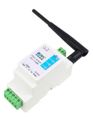
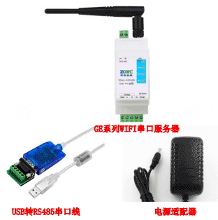
- One ZQWL-GE300D device, Wi-Fi version.
- One AC/DC 12 V 1 A power adapter. Prepare a separate power supply if real sub-devices are connected.
- One serial or USB-to-RS485 adapter.
- Several RS485 A/B wires. Common wires are enough for testing.
- One PC.
If you need to test real device reporting, prepare additional Modbus sub-devices, such as a temperature and humidity transmitter or air-quality transmitter.
2.2 Software preparation
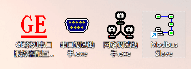
Prepare the GE serial-server configuration tool V218, a serial debugging assistant, a network debugging assistant, and Modbus Slave.
2.3 Network configuration
Use a laptop or a PC with a wireless network adapter to search for the Wi-Fi name ZQWL-GE-XXXXXX. Connect to it with password 12345678 and wait for the connection to succeed.
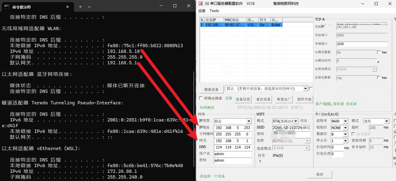
After connection, use the GE serial-server configuration tool to search for the device.
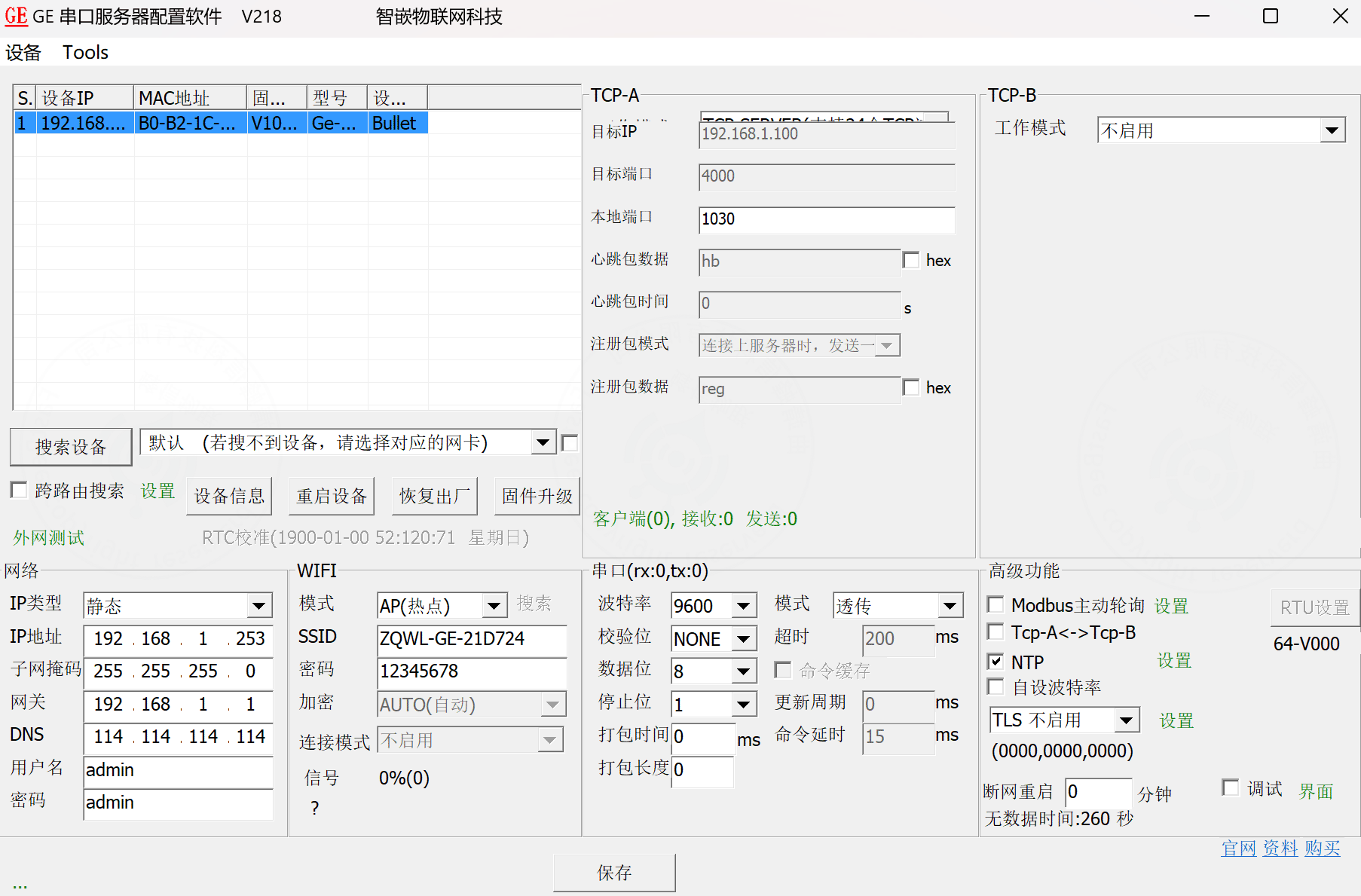
The device can be configured to connect to a router.
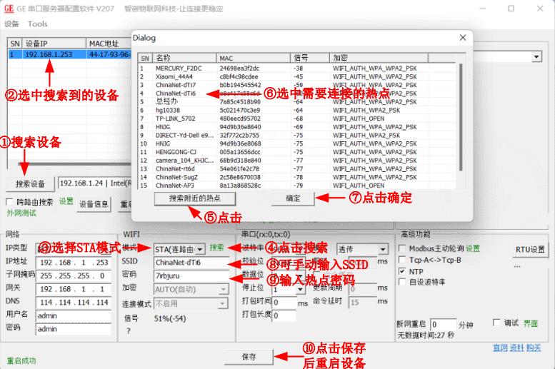
Configure the device network:
- Dynamic IP can be selected directly. Keep the device and laptop in the same LAN.
- If static IP is used, make sure the device IP and laptop IP are in the same network segment. Modify either the device IP or the laptop IP when needed.
The following example changes the device IP so it stays in the same network segment as the laptop.
You can also refer to the official device documentation and use the mobile app for network provisioning. This guide does not demonstrate the app-based method.
2.4 Simulate Modbus sub-devices
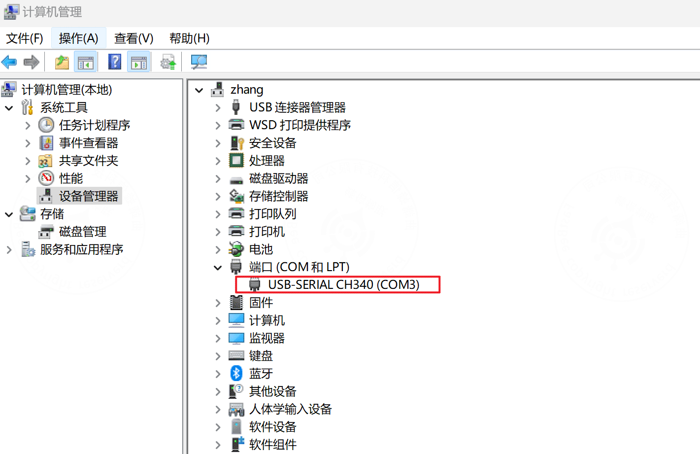
After the device is powered on, insert the USB-to-RS485 adapter into the PC and check the assigned serial port. In this example, the adapter uses COM3.
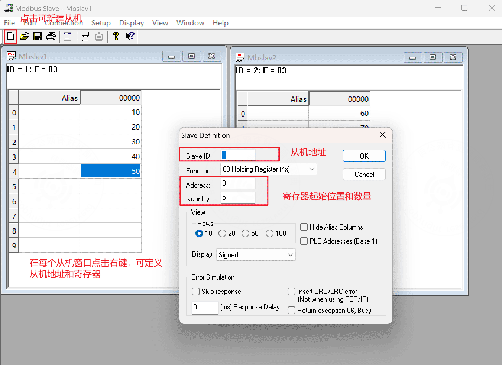
Open the Modbus Slave simulator and configure the simulated Modbus sub-device.
Important
The serial parameters configured here must be the same as the RS485 parameters configured on the gateway device.
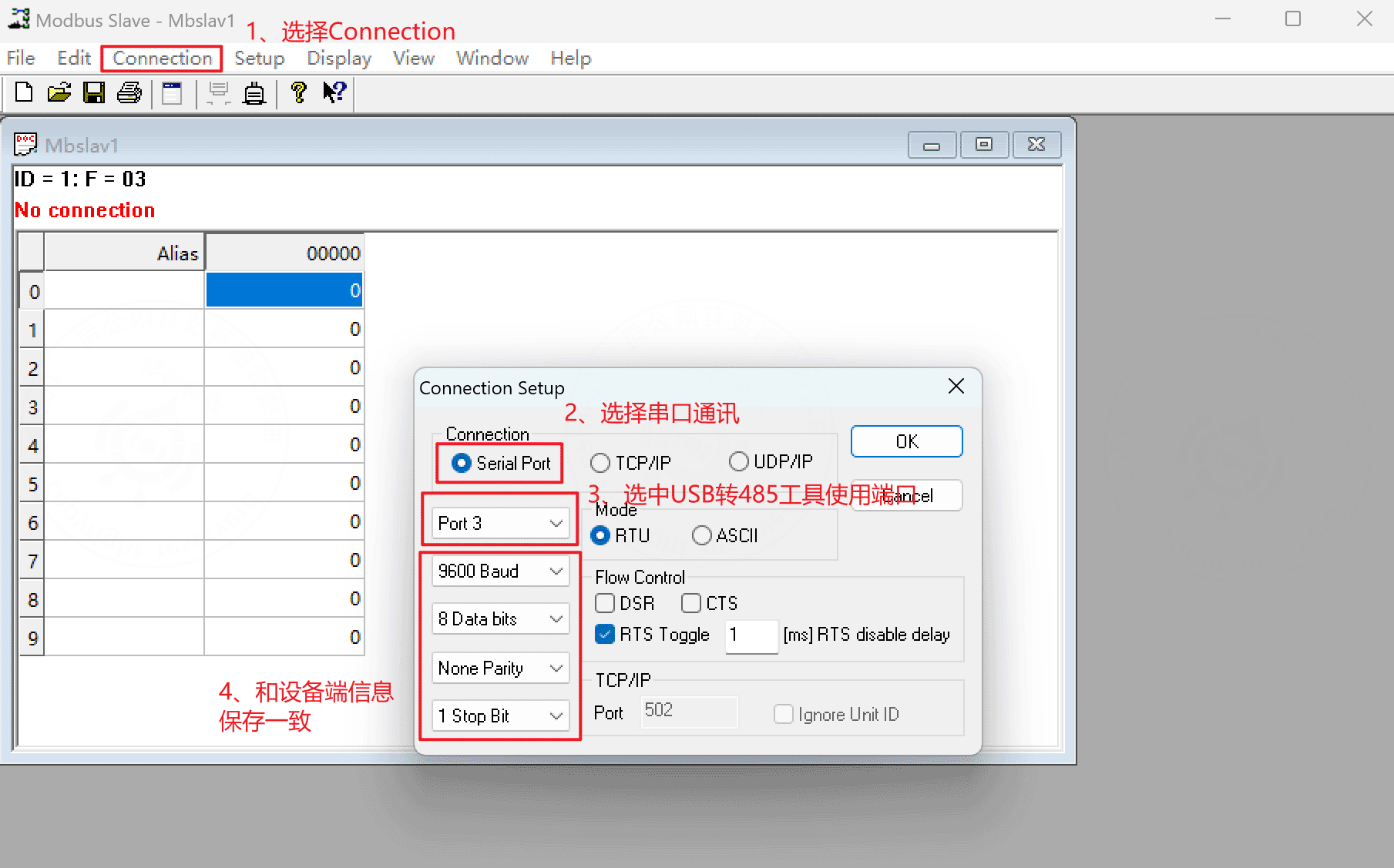
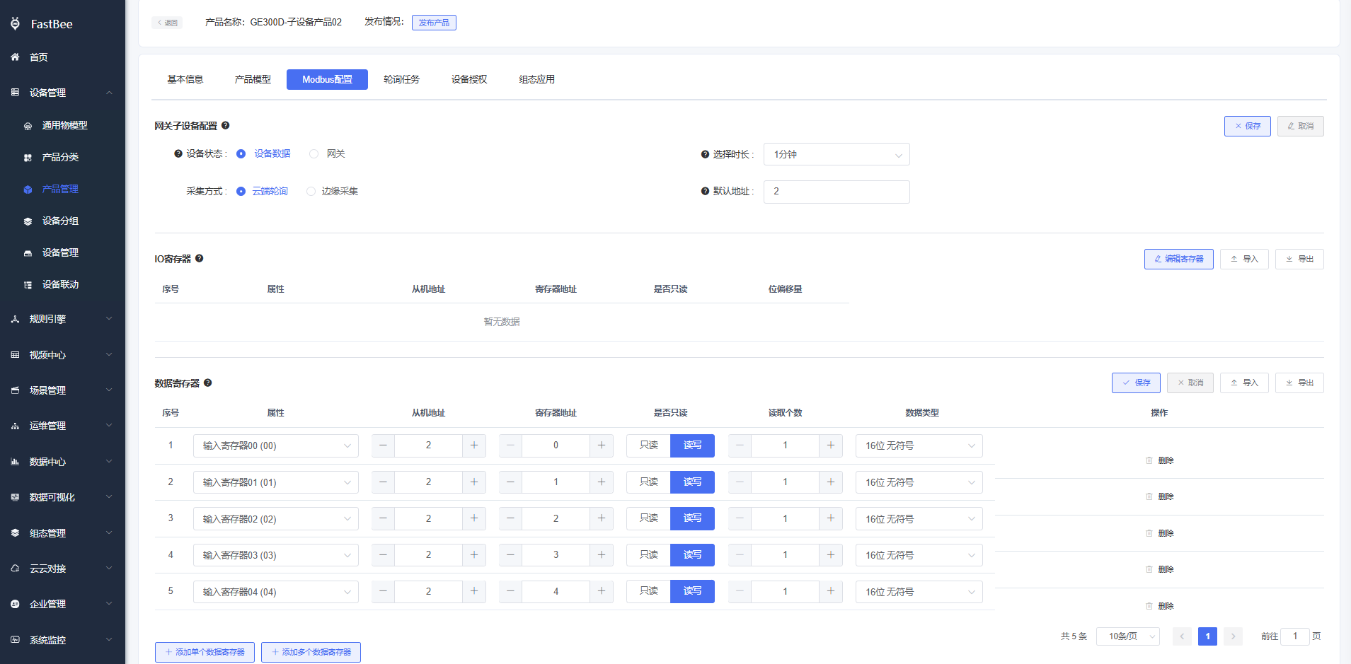
Configure registers and register values. This demo uses two slaves, 1 and 2, with five registers for each slave.
2.5 Platform configuration
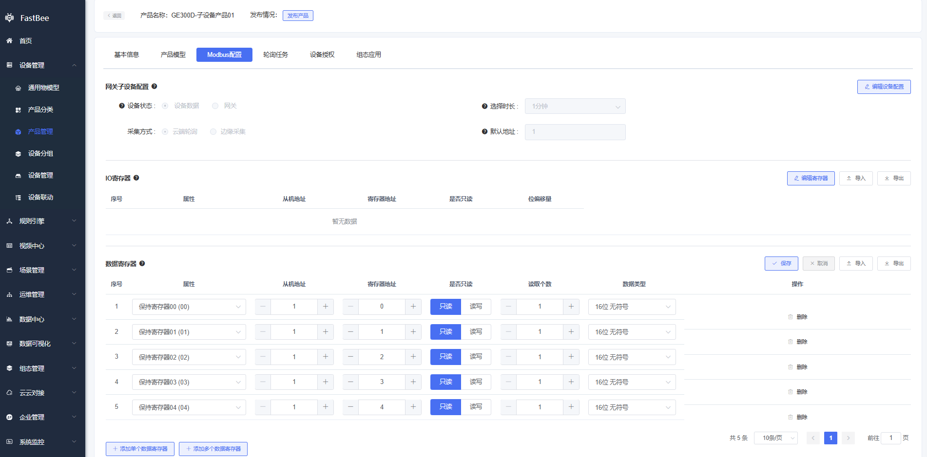
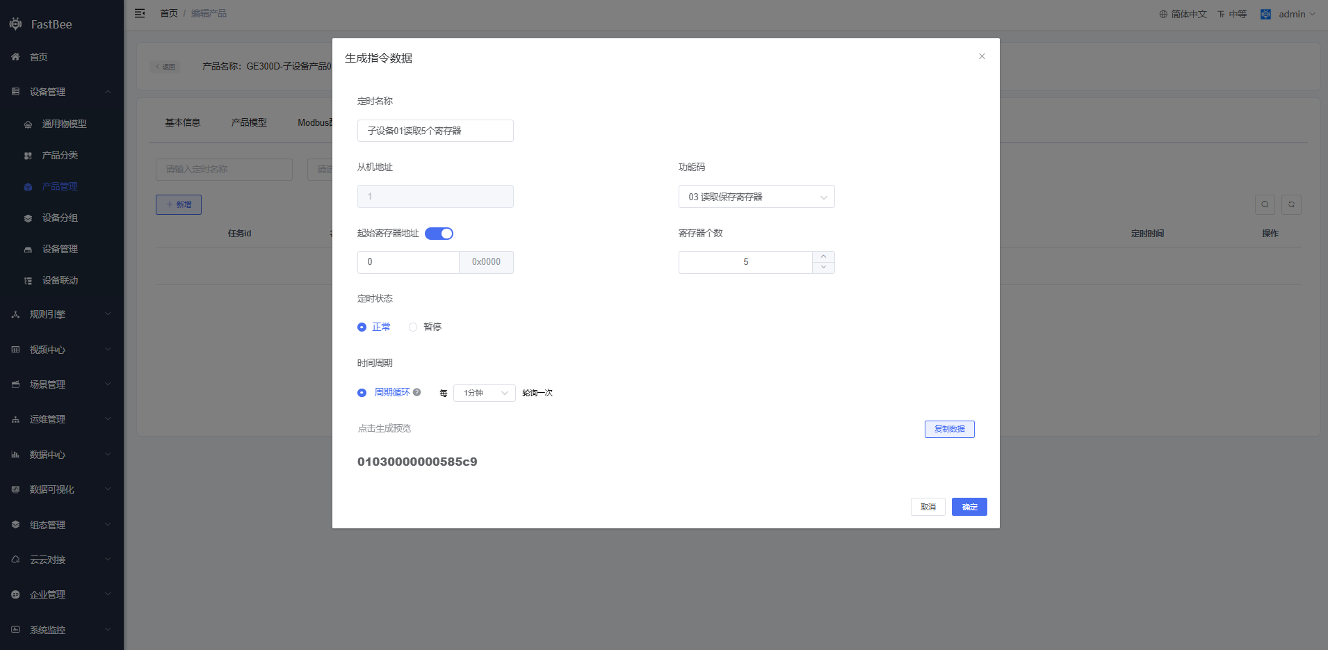
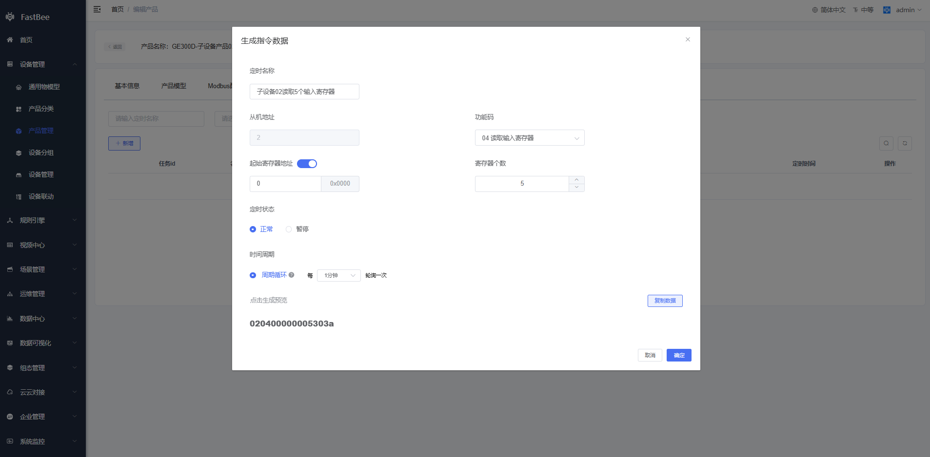
Create a collection-point template and select cloud polling.
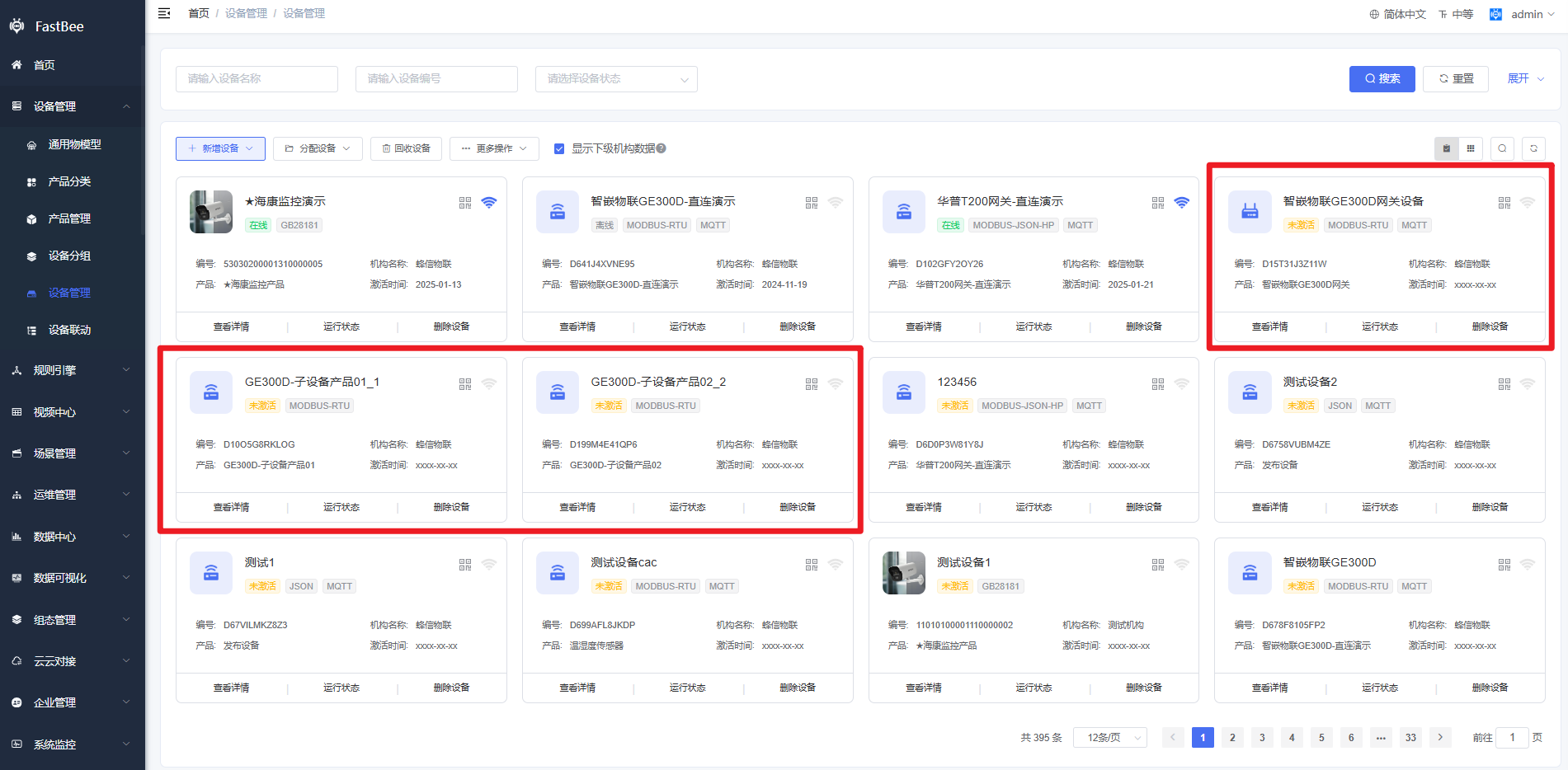
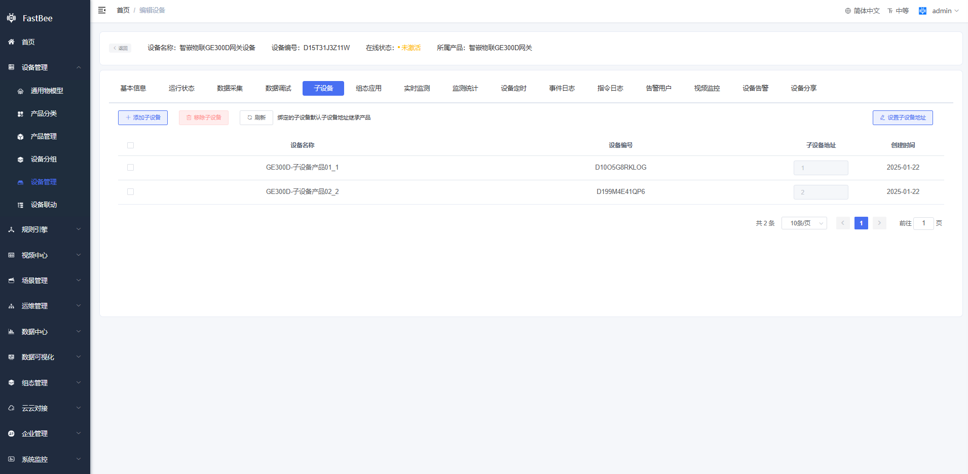
Add slaves. The slave address must be the same as the address configured in the Modbus simulator.
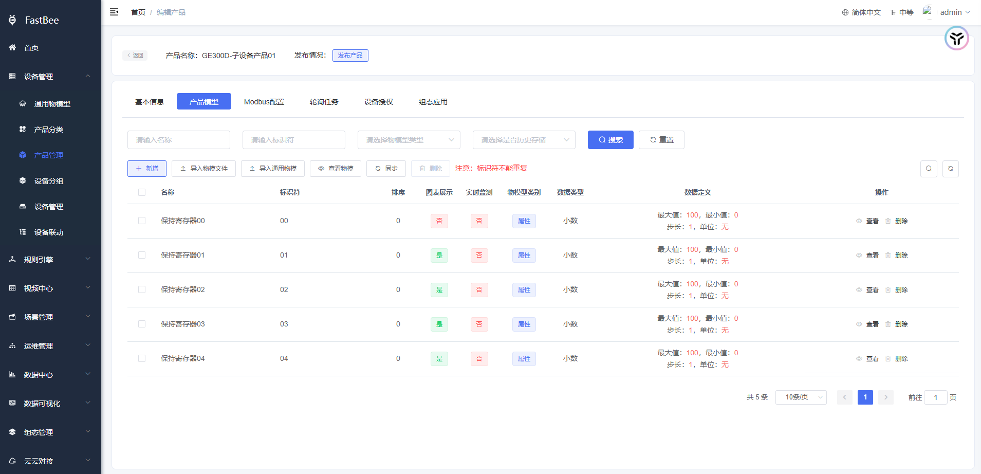
Add thing models for the slave devices. The model identifier is associated with the register address.
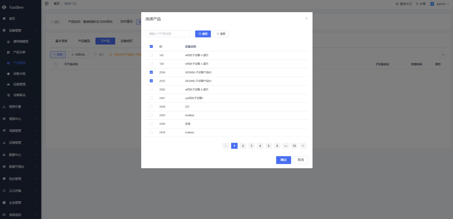
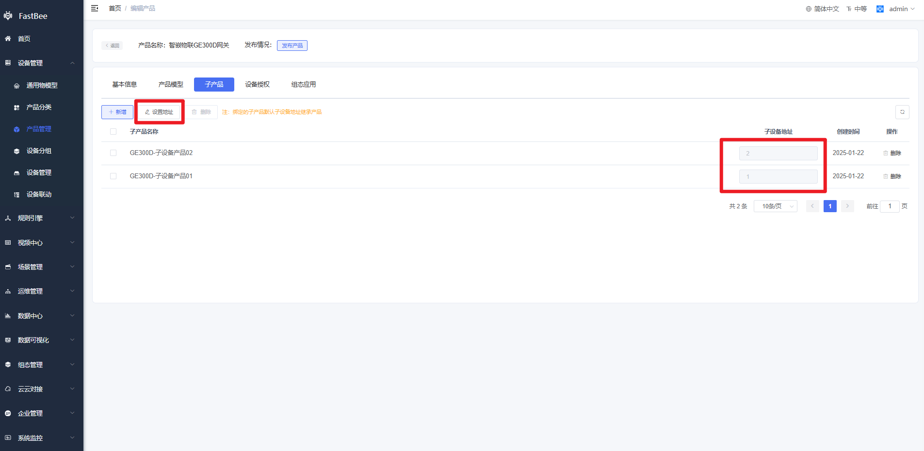
The final configuration contains two slaves, with slave addresses 1 and 2.
- Sub-device 01 thing models map to register addresses
0-4. - Sub-device 02 thing models map to register addresses
5-9.
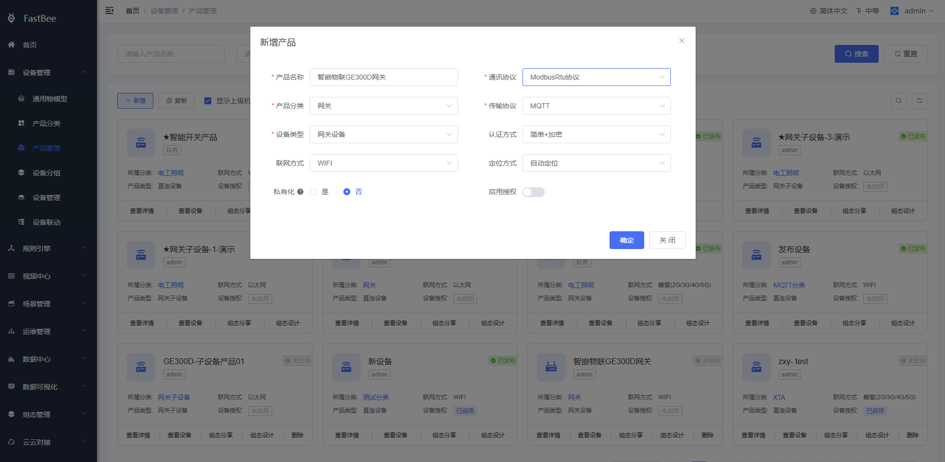
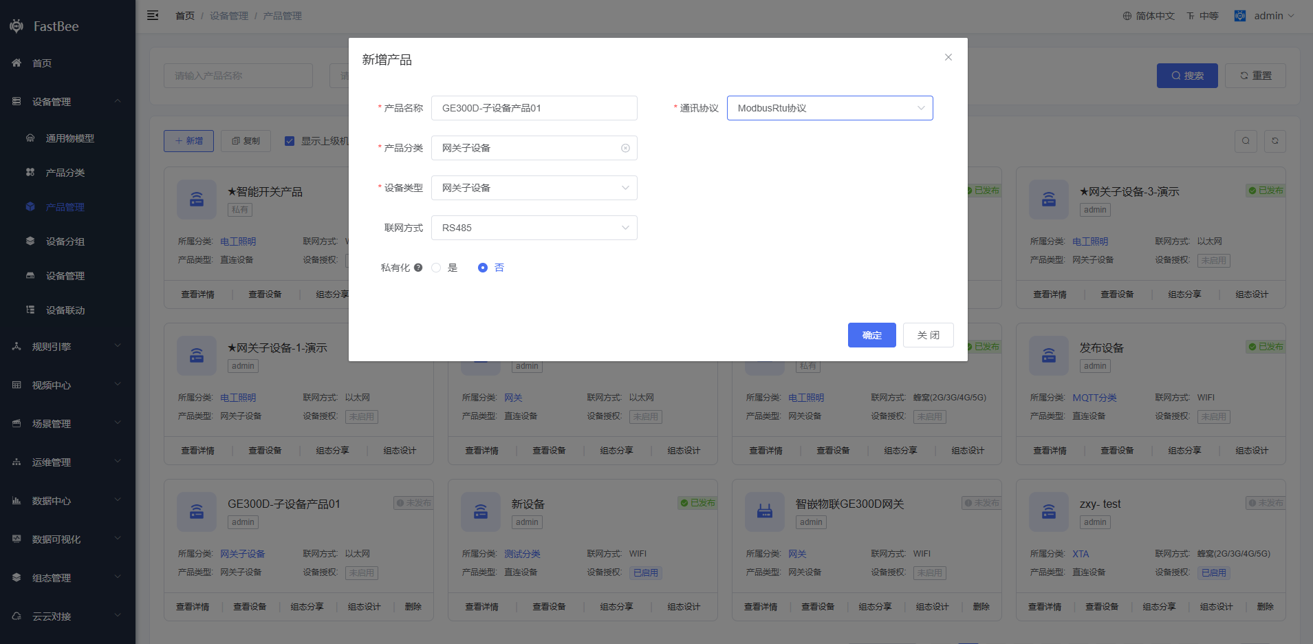
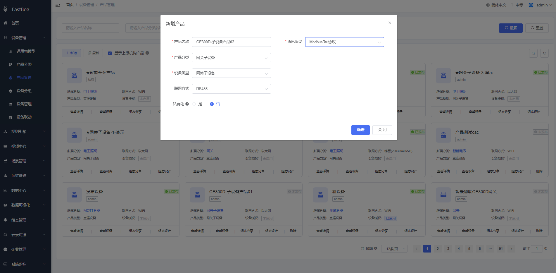
Create a product based on the collection-point template. Select the communication protocol and transport protocol as shown below:
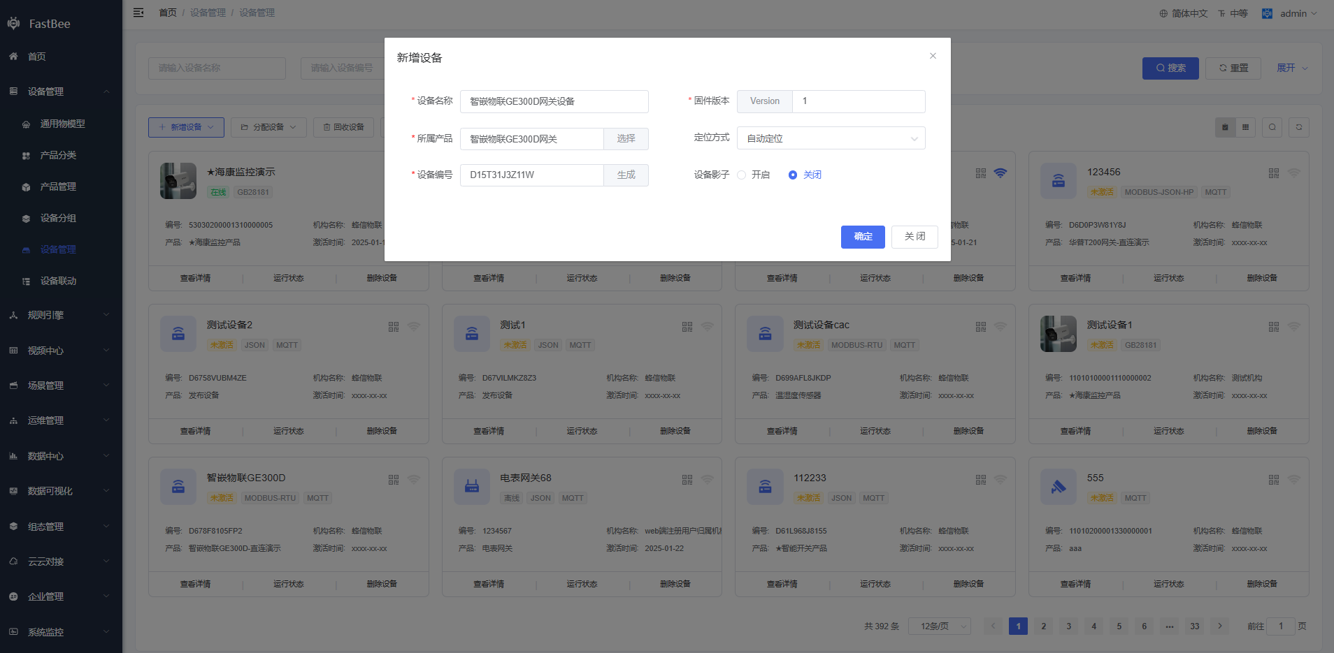
Create a device:
2.6 Device-side configuration
Use the GE serial-server configuration tool. Set TCP-A working mode to MQTT, save the configuration, and restart the device.
Publish topic, device -> cloud:
/{productId}/{clientId}/property/post
/2244/D13QN3R79D12/property/post
Subscribe topic, cloud -> device:
/{productId}/{clientId}/function/get
/2244/D13QN3R79D12/function/get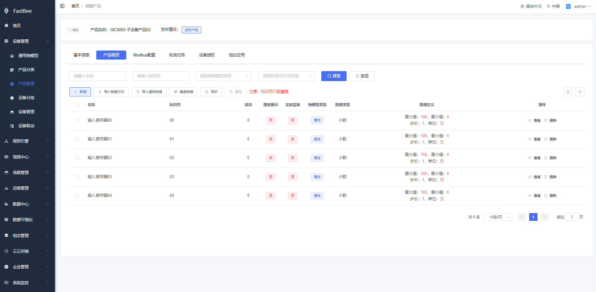
2.7 Verify real-time polling
After power-on, the device should be online.
Check the polling data of the sub-devices. If the simulated values and platform real-time polling values match, cloud polling is working.
2.8 Connect a real sub-device
This example uses a Zhiqian IoT temperature and humidity transmitter.
Set the slave address to 1 and communication mode to RS485. The humidity register address is 0x0000, and the temperature register address is 0x0001.
This corresponds to slave 1 in the collection-point template:
- Humidity thing model -> register address
0. - Temperature thing model -> register address
1.
Connect the device as shown below:
The cloud platform can now display real-time data from the sub-device through cloud polling.
3. Other access methods
Other access methods can be configured according to the device protocol support and project requirements.