HP-ERS-T200V2 access guide
1. Device overview
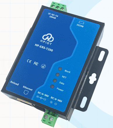
The HP-ERS-T200V2 is an industrial DTU / gateway device. It is suitable for connecting Modbus sub-devices to FastBee through MQTT or TCP.
Main capabilities:
- Supports MQTT and TCP protocols. Each connection supports one socket backup, registration packet, and heartbeat packet.
- Supports Modbus-to-JSON conversion, with up to 128 variables.
- Supports configuration through web UI, serial AT commands, and the PC configuration tool.
- Provides RS232 and RS485 interfaces.
- Supports 12-36 V wide-voltage power supply.
- Industrial design with software and hardware watchdogs.
2. Preparation
Hardware
- One HP-ERS-T200V2 device, Ethernet version with network cable.
- Three DC 12 V 1 A power adapters. Two are required when connecting real sub-devices.
- One serial or USB-to-RS485 adapter.
- One PC.
- Several RS485 A/B wires. Common wires are enough for testing.
If you need to test real device reporting, prepare additional Modbus sub-devices such as a temperature and humidity transmitter or an air-quality transmitter.

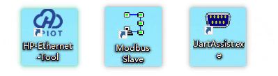
Software
- HP-Ethernet-Tool V0.0.10.exe, used when the device IP address needs to be changed.
- Modbus Slave simulator.
- Serial assistant.
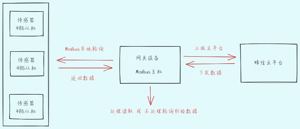
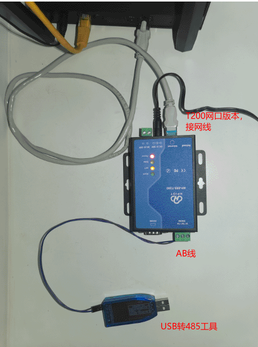
The access topology is shown below:
3. Network configuration
The default device IP address is 192.168.1.200, which is also marked on the device body.
Connect the device to the same network as the PC. If you use the default IP address, you can skip the IP change step.
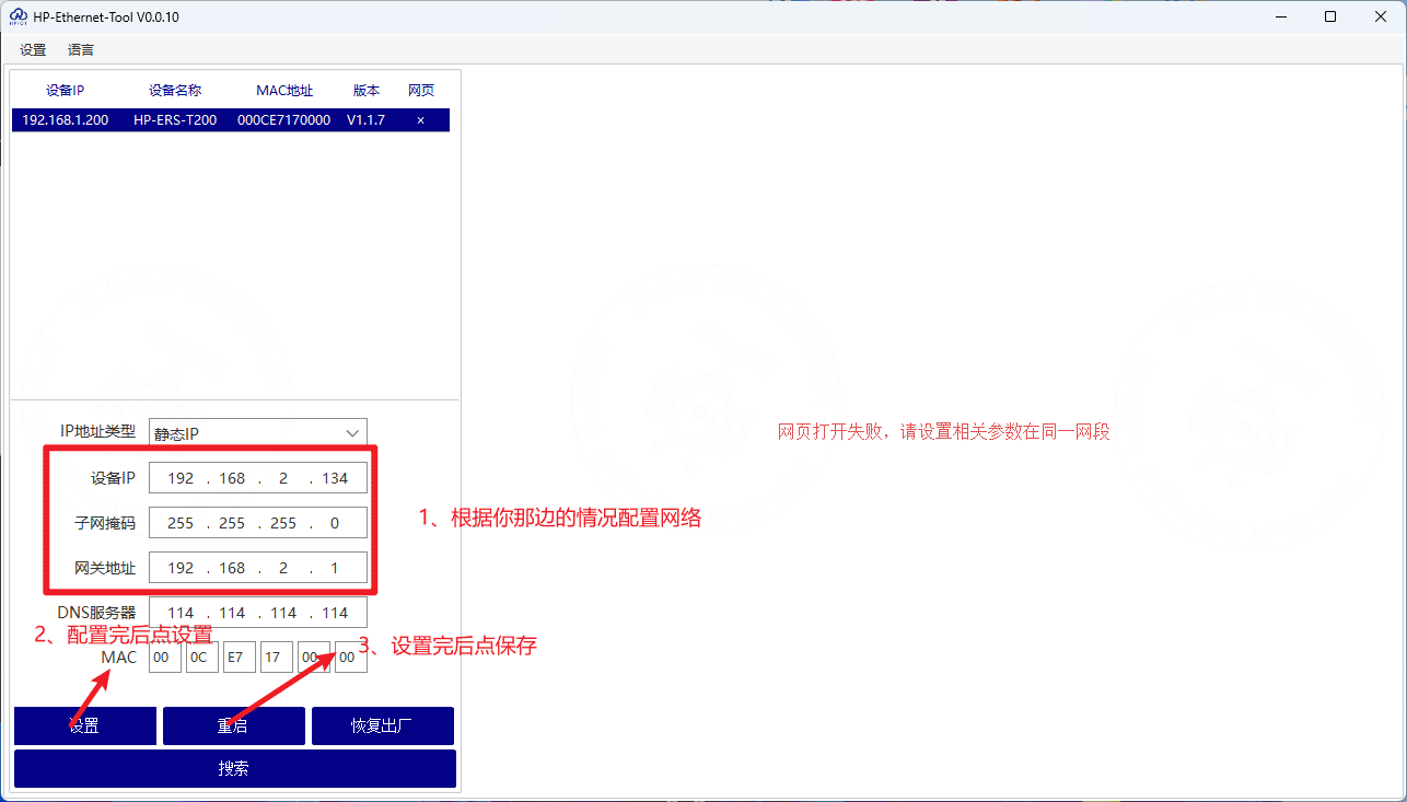
3.1 Change the device IP address
Open HP-Ethernet-Tool V0.0.10.exe and search for the device on the same network.
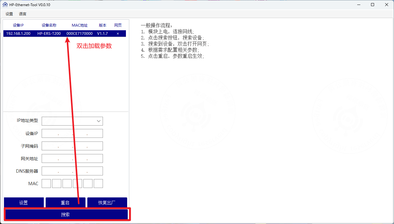
After the device is found, set the target IP address, for example 192.168.x.xxx. Keep other parameters as default unless your network requires a specific configuration. The MAC address is printed on the device body.
4. Simulate Modbus sub-devices
4.1 Wiring and simulator configuration
Prepare the hardware wiring as shown below:
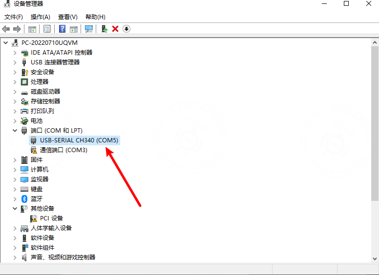
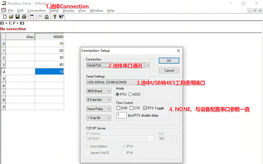
After inserting the USB-to-RS485 adapter into the PC, check the assigned serial port. In this example, the adapter uses COM5.
Open the Modbus Slave simulator and configure the serial parameters.
Important
The serial parameters configured here must be the same as the RS485 serial parameters configured on the gateway device.
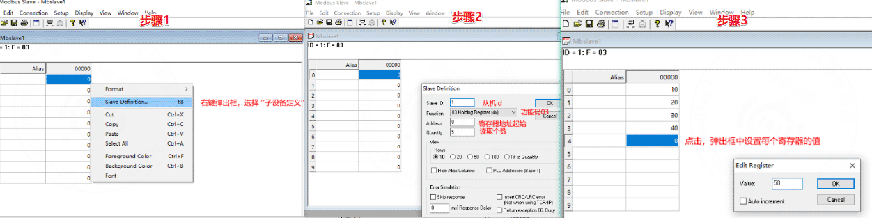
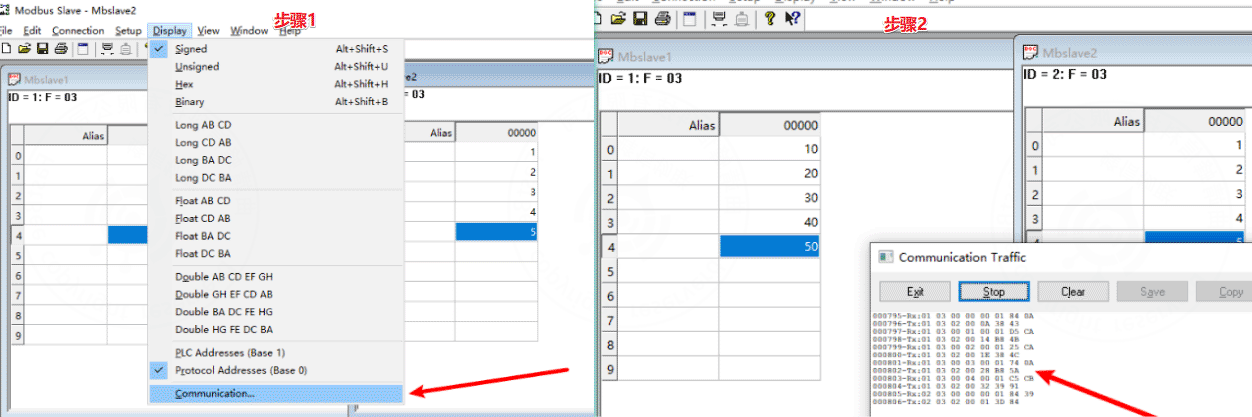
Configure registers and register values. In this example, registers 0-4 are assigned values 10-50.
To demonstrate multiple sub-devices, add another slave device in the simulator.
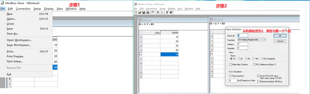
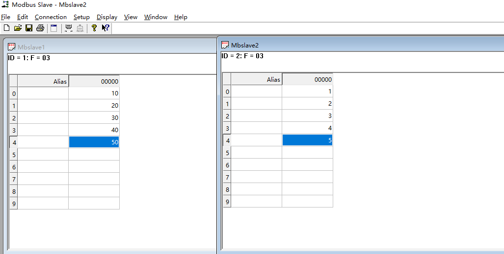
The final simulator configuration contains two Modbus slaves:
5. FastBee platform configuration
5.1 Create a collection-point template
After the Modbus simulator is ready, configure the cloud platform. Create a collection-point template first.
- Select the edge-gateway mode.
- The slave address must be the same as the slave ID configured in the Modbus simulator.
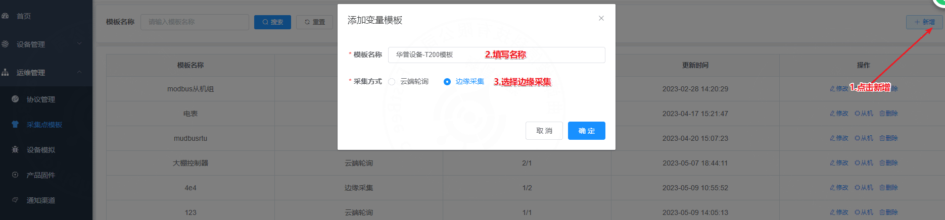
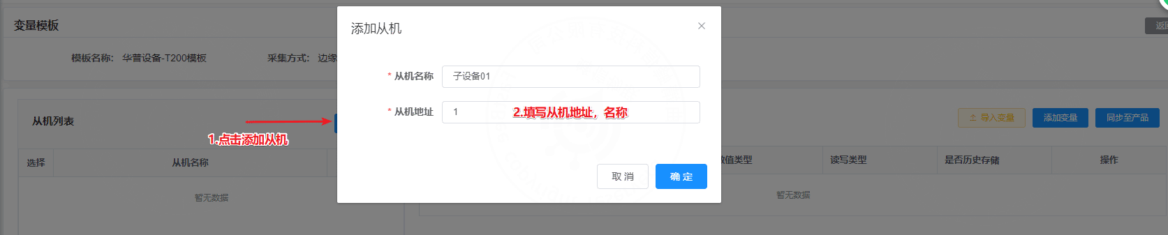
Add a sub-device. In this example, the slave address is 1.
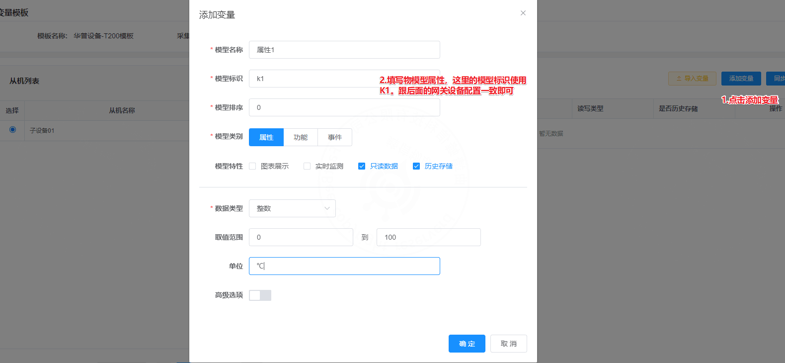
Add the thing model for the sub-device. The model identifier is associated with the register address.
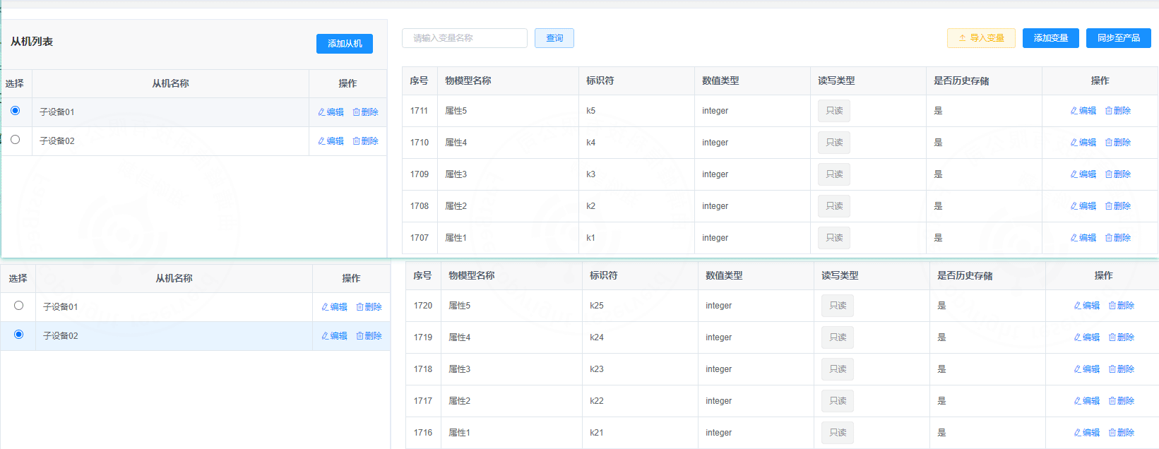
The final template contains two slaves. Slave addresses are 1 and 2. Sub-device 01 uses thing model identifiers k1-k5, and sub-device 02 uses k21-k25.
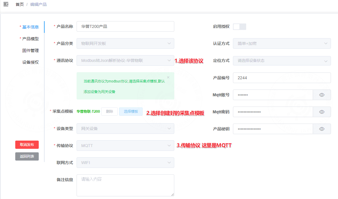
5.2 Create a product
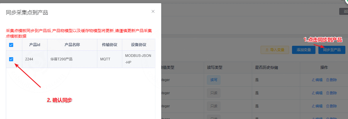
Create a product based on the collection-point template.
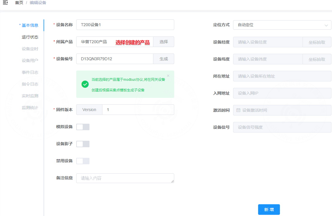
5.3 Create a device
Create the gateway device under the product.
6. Device-side configuration
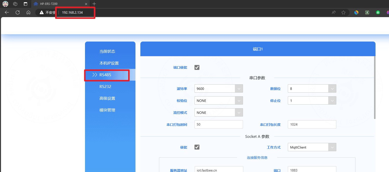
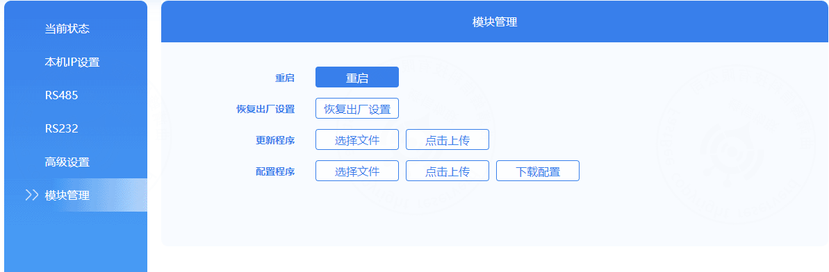
6.1 Configure the device in a browser
If the device IP address has not been changed, open http://192.168.1.200 in a browser. If the IP has been changed, open the new address.
Important
The RS485 parameters on this page must be the same as the parameters configured in the Modbus simulator.
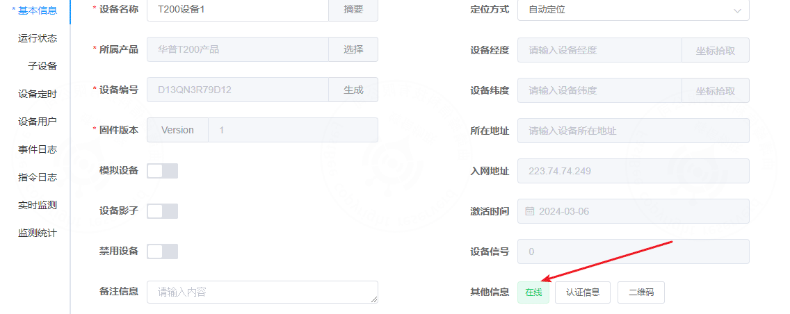
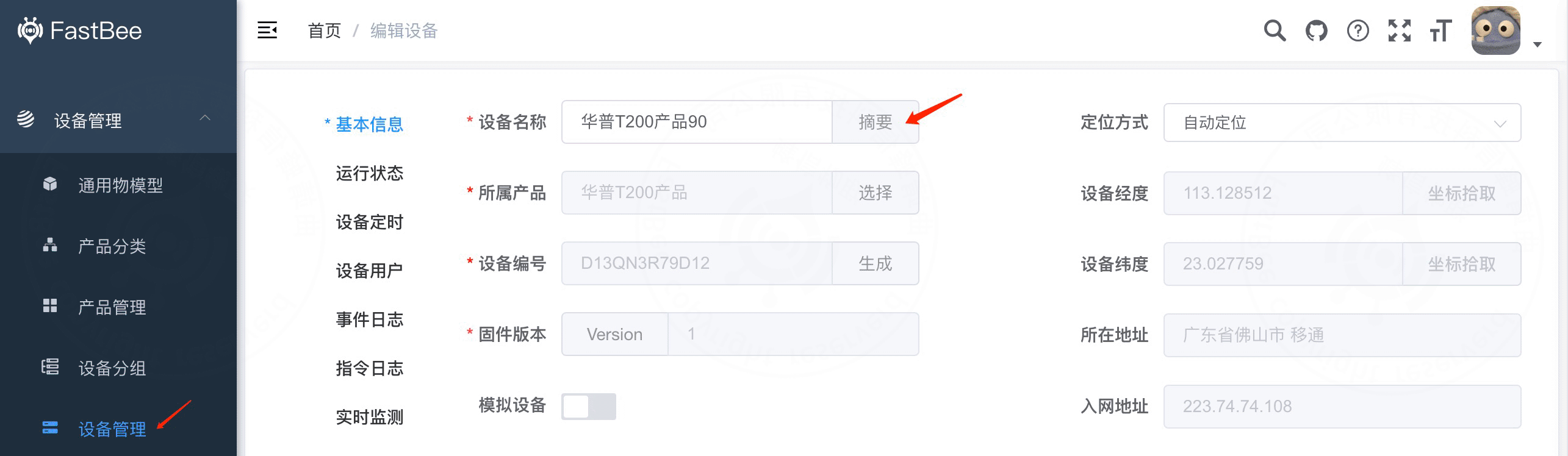
6.2 Obtain MQTT authentication information
Open the device basic information page in FastBee and view the authentication information.
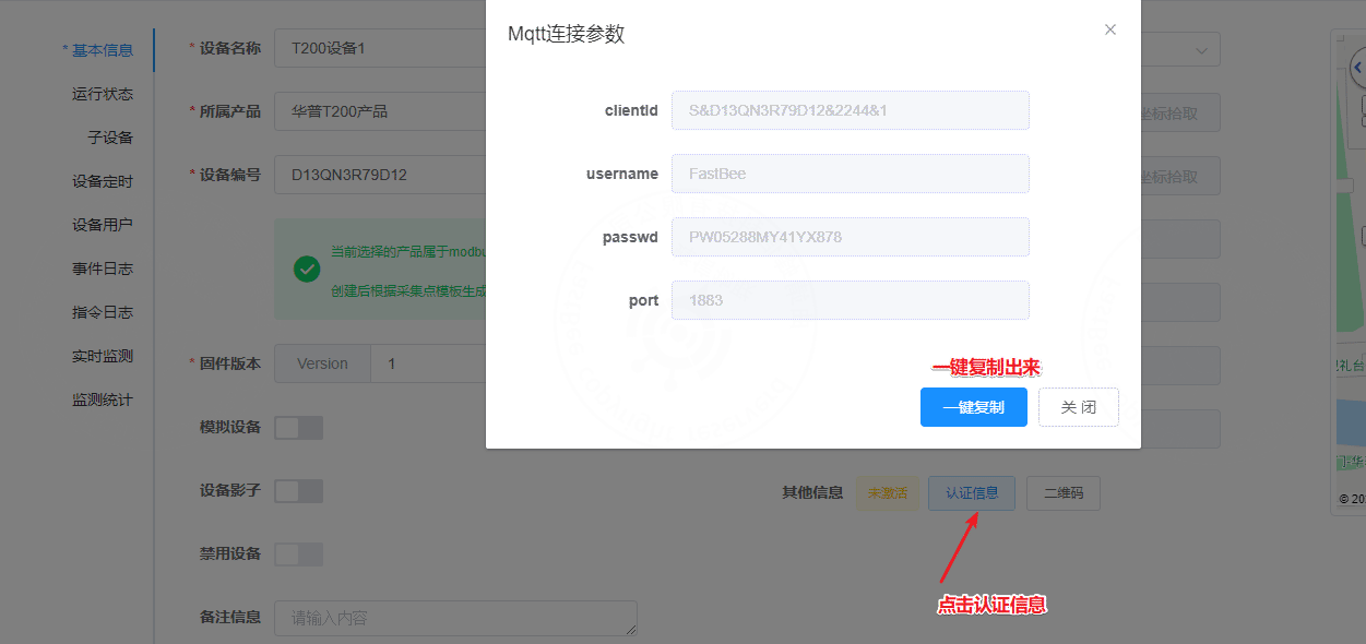
The platform provides clientId, username, password, and port.
{
  "clientId": "S&D13QN3R79D12&2244&1",
  "username": "FastBee",
  "passwd": "PW05288MY41YX878",
  "port": 1883
}
6.3 Configure MQTT connection information
When filling in the device configuration, replace every & in clientId with $$.
S&D13QN3R79D12&2244&1
S$$D13QN3R79D12$$2244$$1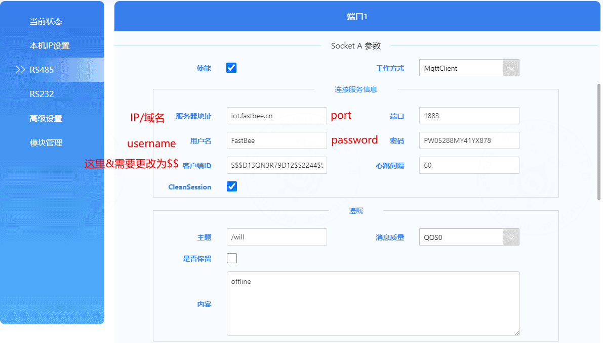
6.4 Configure MQTT publish and subscribe topics
If you customize topics, you can adapt them through the platform rule engine.
Publish topic, device -> cloud:
/{productId}/{clientId}/property/post
/2244/D13QN3R79D12/property/post
Subscribe topic, cloud -> device:
/{productId}/{clientId}/function/get
/2244/D13QN3R79D12/function/get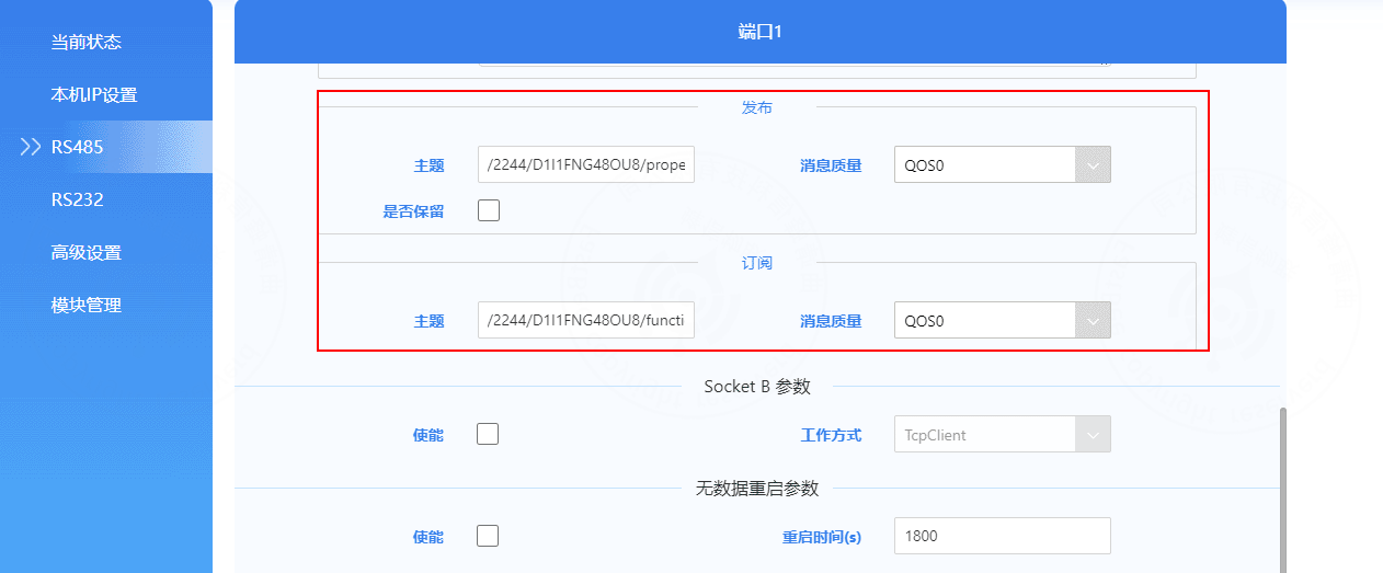
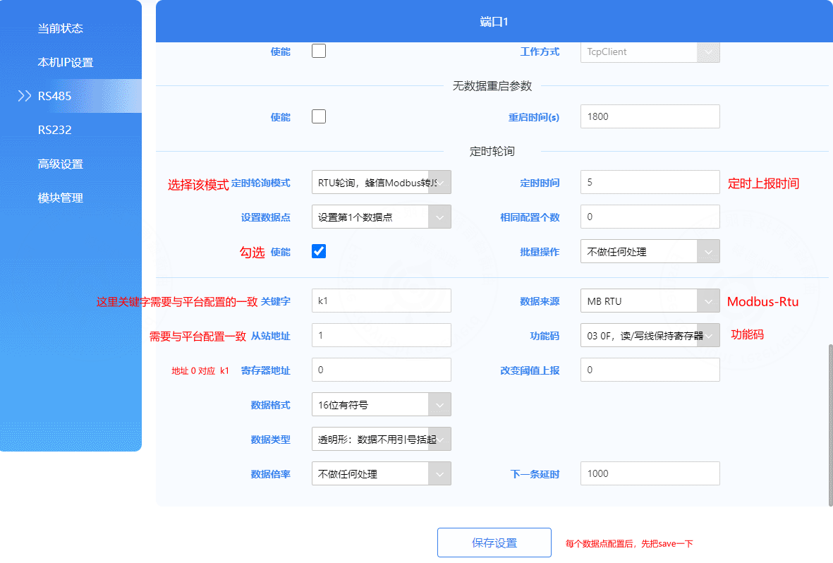
6.5 Configure periodic polling
Set the polling mode to FastBee Modbus-to-JSON and configure the data points.
Key fields:
- Polling interval: in seconds. Set the collection interval as needed.
- Data points: up to 200 points are supported.
- Enable: enable the point before editing it.
- Keyword and register address: for example,
k1is bound to register address0; it must match the thing model identifier in the collection-point template. - Slave address: must match the slave address in the collection-point template.
- Register address: the Modbus data point address.
- Function code: for example, function code
03reads holding registers. Other codes include01,02,04, and10. - Data format: select according to the sub-device specification. The default is usually 16-bit signed integer.
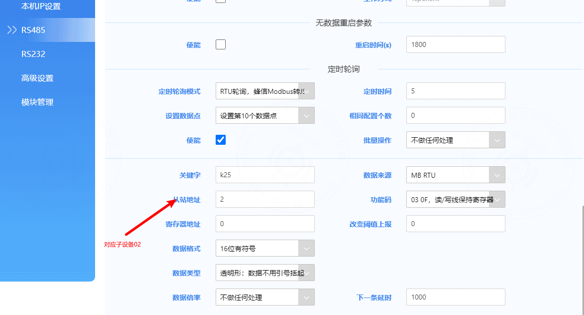
Configure five collection points for slave 2:
Restart the device after configuration so the settings take effect:
Check the Modbus simulator logs. If the simulator receives polling logs, the configuration is effective.
7. Verify data collection
The gateway device should now be online.
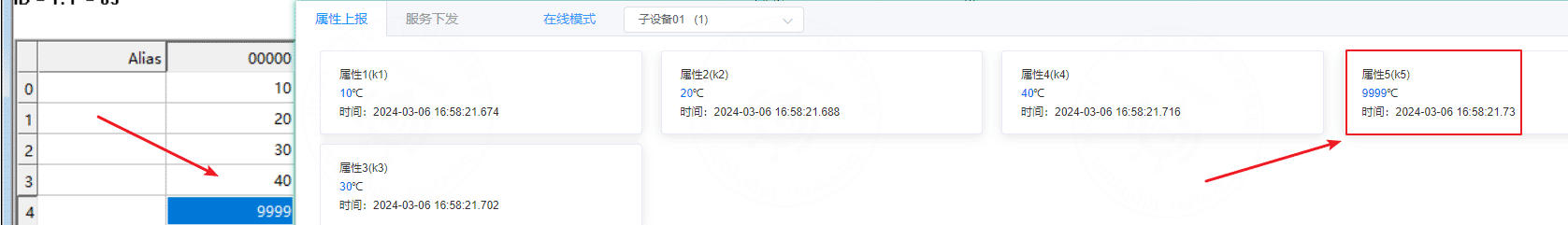
Check the values configured in the simulated devices:
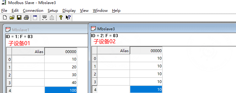
Then check the real-time platform data:

Change the value in the Modbus simulator and observe the platform data again. If the platform value changes, real-time collection and reporting are working correctly.
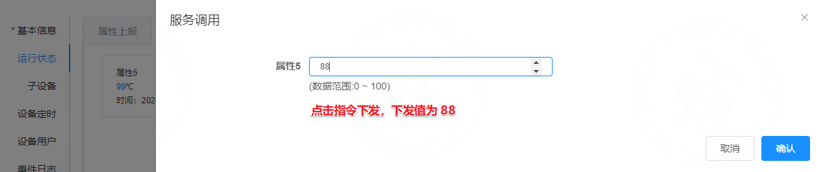
8. Verify command delivery
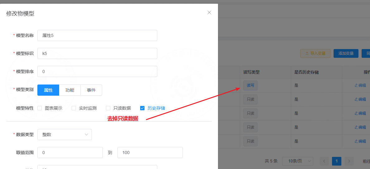
Change one property to a readable and writable property.
Open the running-status page and send a command.
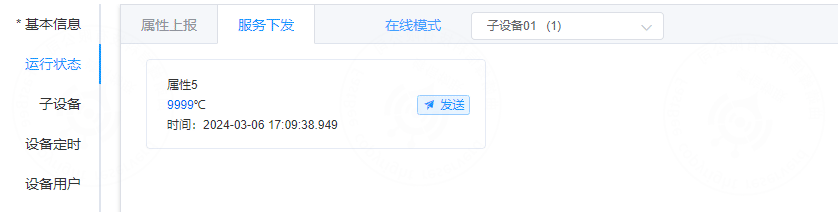
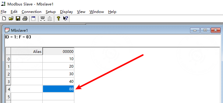
Check the simulator. The value of the simulated sub-device should change.
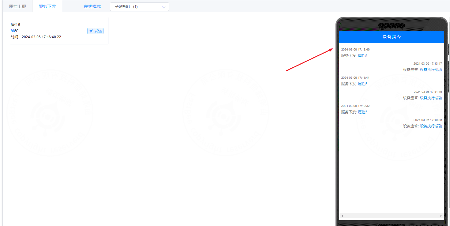
The command delivery logs should show successful writes.
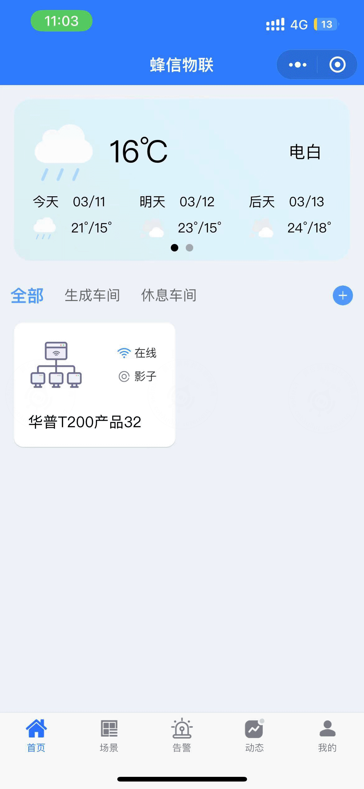
9. Mini Program access
The mobile side includes WeChat Mini Program, Android, iOS, and H5. This example uses the WeChat Mini Program.
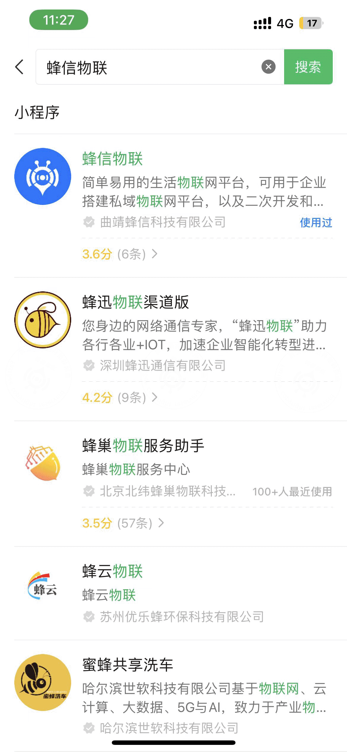
9.1 Add the Mini Program
Search for and add the FastBee IoT Mini Program in WeChat.
9.2 Prepare the QR code
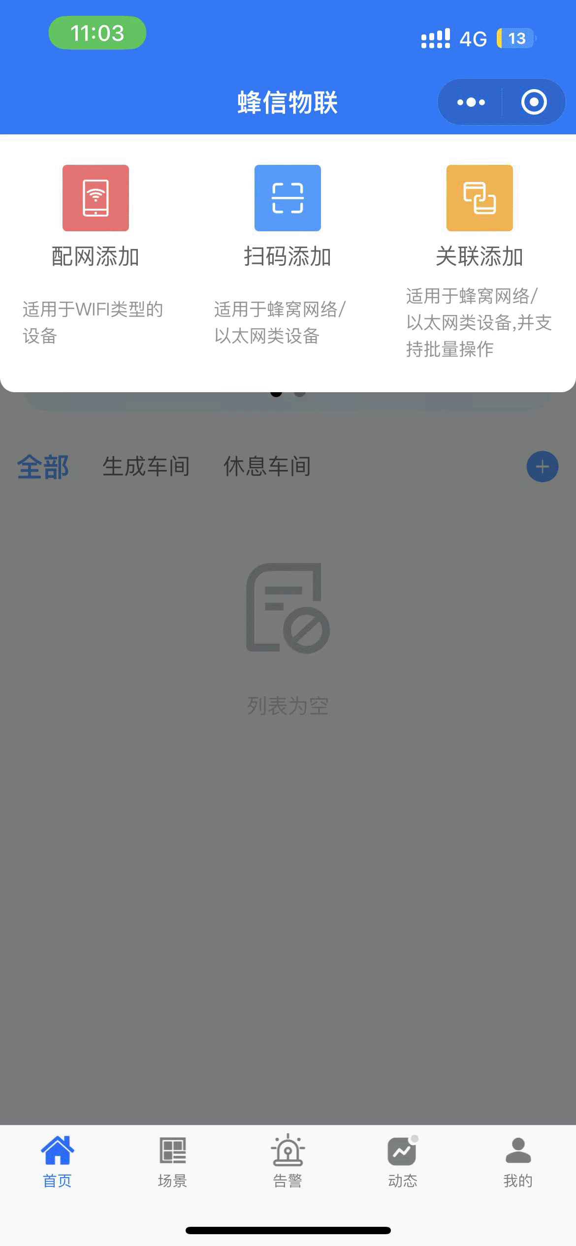
Tap the + button in the upper-right corner of the Mini Program to add a device.
The Mini Program supports three methods:
- Provisioning
- Scan to add
- Association
This example uses Scan to add. Prepare the QR code from the platform device page.

9.3 Scan and add the device
Select Scan to add and scan the QR code.
After scanning succeeds, the device is added to the account.