IEC 104 protocol
IEC 60870-5-104 protocol
1. IEC 104 overview
1.1 Protocol summary
IEC 60870-5-104, commonly called IEC 104, is a power-industry communication protocol based on TCP/IP. It is mainly used for remote data monitoring and control.
A typical communication system contains:
- A slave server that sends data and receives commands.
- A master client that receives data and sends commands.
IEC 104 uses response-based data transmission. Upstream data usually includes remote signalling and telemetry. Downstream data usually includes remote control and remote adjustment.
1.2 IEC 104 frame format
The common IEC 104 frame format is shown below:
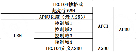
APCI is the control information part. ASDU is the application service data unit. APDU length equals APCI + ASDU - 2, excluding the start byte and the APDU length byte.
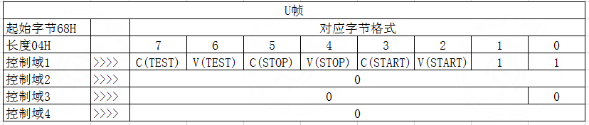
IEC 104 has three frame types:
- U frame: control frame.
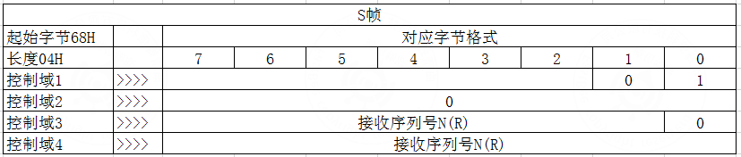
- S frame: supervisory frame.
- I frame: information transfer frame.
The U frame contains only APCI and is mainly used for start, stop, and test frames.
The S frame also contains only APCI.
The I frame contains APCI and ASDU.
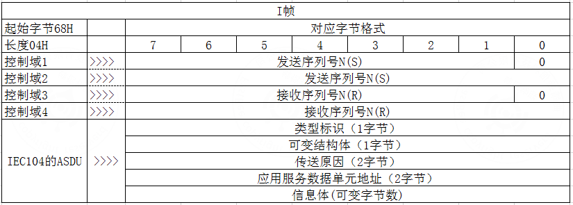
Important fields:
- Send sequence number and receive sequence number ensure data integrity.
- Type identification defines the format of transmitted data.
- Variable structure qualifier defines whether information objects are ordered or unordered. Ordered data uses one information object address, and element addresses increase by 1 from that base address. Unordered data maps one address to one element.
- Cause of transmission records why the data is transmitted and classifies transmission data.
1.3 IEC 104 communication flow
- The client establishes a connection to the server and sends a link-start frame.
- After receiving the link-start frame, the server sends a start confirmation frame.
- After receiving the start confirmation, the client sends a general interrogation request frame.
- The server responds to the general interrogation request, then sends general interrogation data. After all data is sent, it sends a general interrogation end frame.
- After receiving the general interrogation end frame, the client sends a time synchronization request frame.
- The server receives the time synchronization request and sends a time synchronization response frame.
- The server actively sends changed-data frames. When control commands are received from the client, the server returns the corresponding operation result.
- The client waits for the next general interrogation cycle and repeats the process from step 4.
2. Master program design
According to project requirements and the IEC 104 communication specification, the master program mainly includes:
- Parsing remote signalling and telemetry data.
- Composing remote control and remote adjustment commands.
- Concurrent database operations.
The implementation involves Java object-oriented programming, multithreading, socket programming, JDBC database mapping, and a C3P0 high-concurrency database connection pool.
The program directory is designed as follows:
jdbc: database connection configuration classes.model: database model mapping classes.dao: database operation classes.iec104.util: utility classes used during processing.iec104: main program logic and processing classes.
The configuration directory contains:
typeId.properties: maps type IDs to readable descriptions for frame parsing.cause.properties: maps transmission-cause values to readable descriptions for frame parsing.remote_signal,remote_measure,remote_control, andremote_adjust: map information object addresses to database fields. They are used to store device status in the matching database model or read command data from the database.
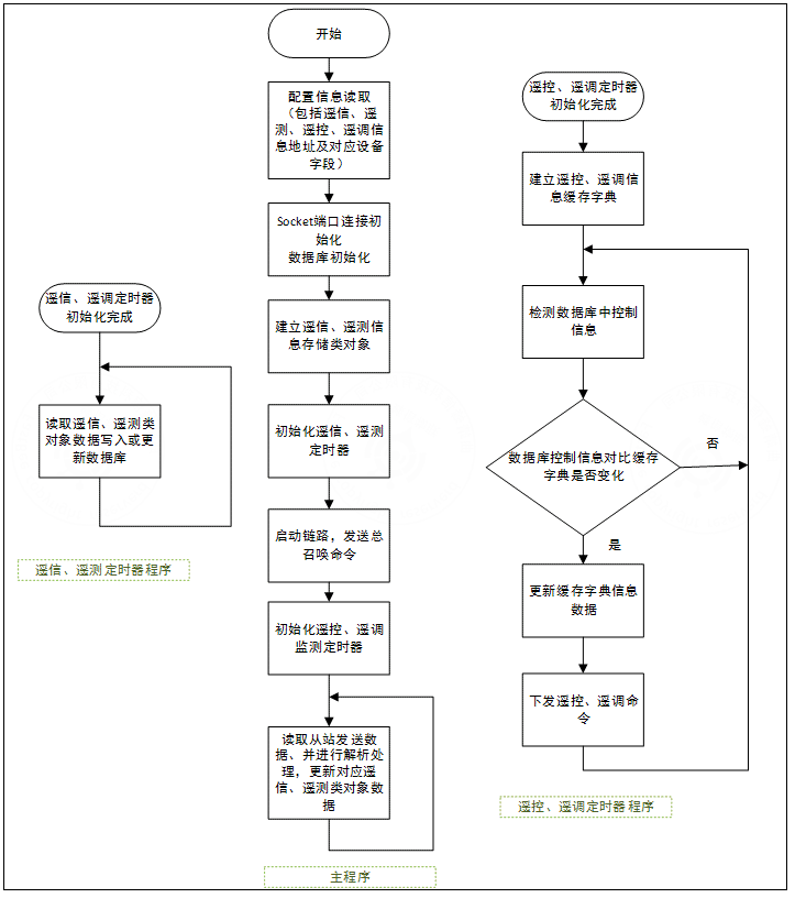
The main program consists of three parts:
- Initialization: configuration loading, socket port initialization, database connection initialization, timer initialization, link startup, and remote signalling / telemetry frame parsing into cache structures.
- Periodic database writing: cached remote signalling and telemetry objects are written to the database periodically.
- Remote control and adjustment timer: database values are compared with cached dictionaries. If a value changes, a command frame is composed and sent.
The overall process is shown below:
3. Database program design
3.1 Device database model classes
The IEC 104 program and the web management system share the same database. The database models required by IEC 104 use the same attributes and fields as the web models. Mapping classes are created under the model package.
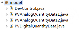
DevControl stores all device information and control data. PVAnalogQuantotyData1, PVAnalogQuantotyData1, and PVDigtialQuantityData are mapping classes for digital and analog information of specific devices, such as photovoltaic inverters.
3.2 Database operation classes
Each model class has a corresponding DAO class. DAO classes define create, update, delete, and query operations.
Core SQL examples from DevControlDao:
-- Add a device.
String sql = "insert into microgrids_devcontrol (num, dev_type) values(?,?)";
-- Update device type.
String sql = "update microgrids_devcontrol set dev_type=? where num=?";-- Delete a device.
String sql = "delete from microgrid_devcontrol where num=?";-- Check whether a device exists.
String sql = "select num from microgrid_devcontrol where num=?";3.3 Database connection initialization
To meet performance requirements during high-volume data writes, the program uses the C3P0 database connection pool. The C3P0Utils class in the jdbc package initializes the MySQL data source.
public class C3P0Utils {
    private static ComboPooledDataSource dataSource = new ComboPooledDataSource("mysql");

    public static DataSource getDataSource() {
        return dataSource;
    }

    public static Connection getConnection() {
        try {
            return dataSource.getConnection();
        } catch (SQLException e) {
            throw new RuntimeException(e);
        }
    }
}
The system reads c3p0-config.xml from the main directory to initialize database settings, including database address, user, and password.
4. Master core program design
4.1 Device information initialization
During initialization, the program loads dev.json. The file contains the device number, device name, and device type ID. The device type ID is defined in the Django model and is written here to make web management easier.
{
  "PVI0101": {
    "name": "PV area 1 inverter 1",
    "DEV_TYPE": 1
  }
}
The program updates device information in DevControl based on this configuration:
- If the device exists in the configuration but not in the database, it is added through
addDev. - If the device exists in the database but not in the configuration, it is deleted through
delDev. - According to the device type ID, the program creates the remote signalling and telemetry data structures required by the device.
These structures are used later to store parsed data.
4.2 Remote signalling and telemetry
During initialization, the program loads remote_signal.json and remote_measure.json. The configuration maps the information object address to database field name, table name, and device number.
{
  "14": {
    "field": "status_down",
    "num": "PVI0101",
    "table_name": "pvdigitalquantitydata",
    "descript": "Xike inverter 1 stopped signal",
    "comment": ""
  }
}
The program uses a Runnable class to write remote signalling and telemetry data structures into the database. It initializes a ScheduledExecutorService, obtains the service object, and periodically executes database writes with scheduleAtFixedRate.
After the general interrogation command is sent, the program continuously reads frames from the slave through the socket and parses them:
Apduparses the start byte, APDU length, send sequence number, receive sequence number, and control-domain information.- The control domain is used to identify the frame as an I frame, S frame, or U frame.
- S frames and U frames usually require little additional handling.
- For I frames,
Asduparses type identification, cause of transmission, common address, and variable structure qualifier. InformationObjectparses the data according to the type identification and stores it inInformationElement.Client#handleDatareads the table name, field name, and device number from the remote signalling or telemetry configuration according to the information object address, then writes the value to the matching device data structure.
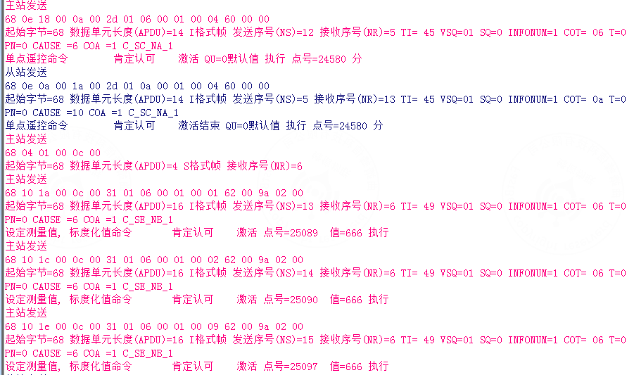
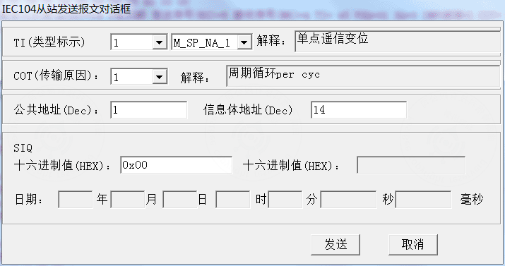
The following example uses PMA software to simulate a slave and test remote signalling.
Start the program, establish the connection, and send the general interrogation command:
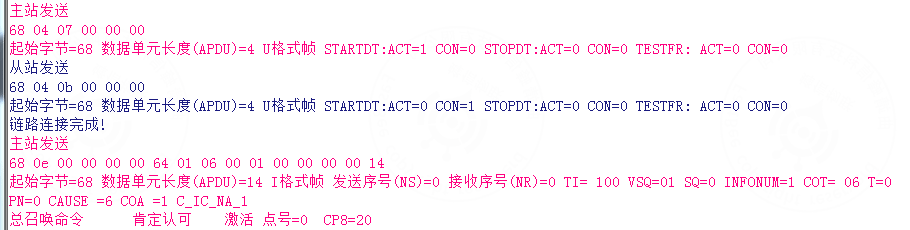
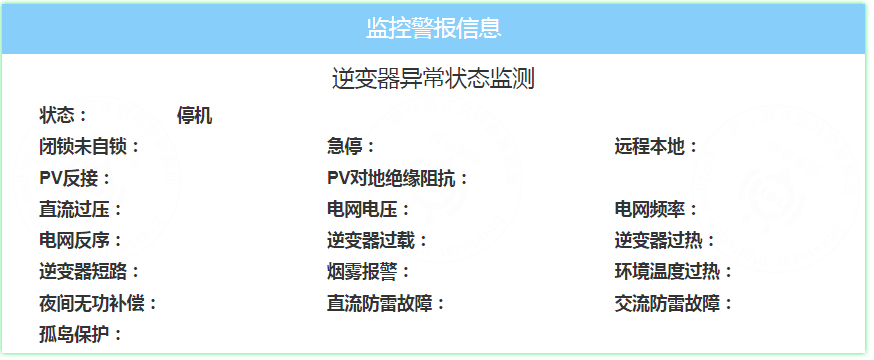
The PMA slave sends a remote signalling value of 0 at address 14, representing the shutdown signal of inverter PV0101.
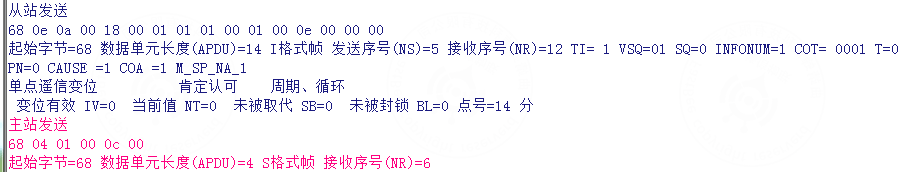
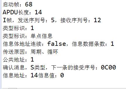
The master receives the remote signalling frame, parses it, and prints the parsed information:
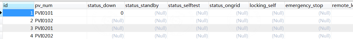
The corresponding database data is updated:
The web management interface shows the updated data for PVI0101:
4.3 Remote control and remote adjustment
During initialization, the program loads remote_control.json and remote_adjust.json. The configuration maps information object address, database field name, and device number.
{
  "25089": {
    "field": "active_power",
    "num": "PVI0101",
    "descript": "Xike inverter 1 active power adjustment value",
    "comment": ""
  }
}
The program defines dictionaries to store real-time remote control and remote adjustment values. Values are recorded so commands are sent only when database values change.
Map<String, Integer> remoteControlValues = new HashMap<String, Integer>();
Map<String, Double> remoteAdjustVlaues = new HashMap<String, Double>();
Then it defines runnable_db_send, a Runnable that composes and sends remote control and remote adjustment frames. A ScheduledExecutorService initializes the timer object service_A, and scheduleAtFixedRate runs the task periodically.
runnable_db_send reads remote_control.json and remote_adjust.json, extracts target values from the database according to address, field, and device number, compares them with remoteControlValues and remoteAdjustVlaues, then updates the dictionary and sends a remote control or adjustment command when a value changes.
The following example uses PMA as the simulated slave.
Modify the control information of inverter PV0101 in the web management interface. The corresponding database value changes.
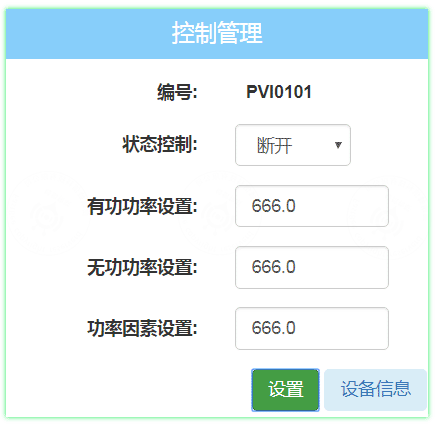
The IEC 104 master sends the matching remote control and adjustment commands and prints the information:
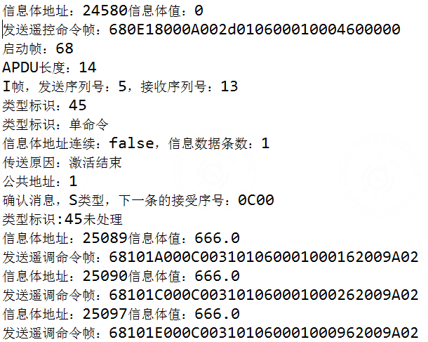
The PMA slave receives the remote control and adjustment information from the IEC 104 master: