
Modbus protocol access
1. Create products and polling tasks
Create a gateway product and a sub-device product first, then establish the topology relationship between the gateway and sub-device. For the topology process, see the Gateway and sub-device document.
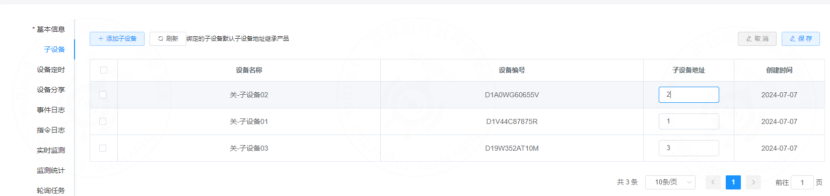
After binding, the topology relationship is shown below:
Next, create polling tasks for the sub-device. The following example uses sub-device 01.
1.1 Open the polling task page
Open Sub-device -> Device details -> Polling task.
1.2 Add a polling task
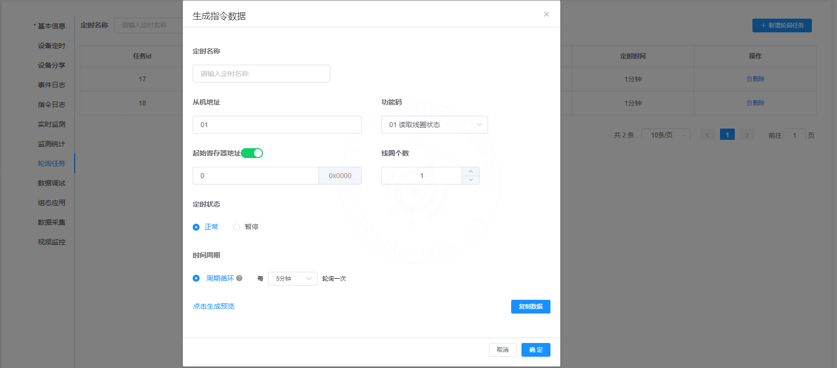
Supported function codes:
Polling interval examples:
| Interval |
|---|
| 1 minute |
| 3 minutes |
| 5 minutes |
| 10 minutes |
| 20 minutes |
| 30 minutes |
| ... |
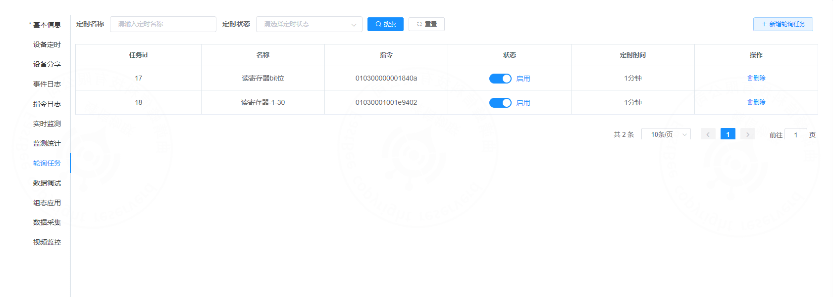
The task list is shown below:
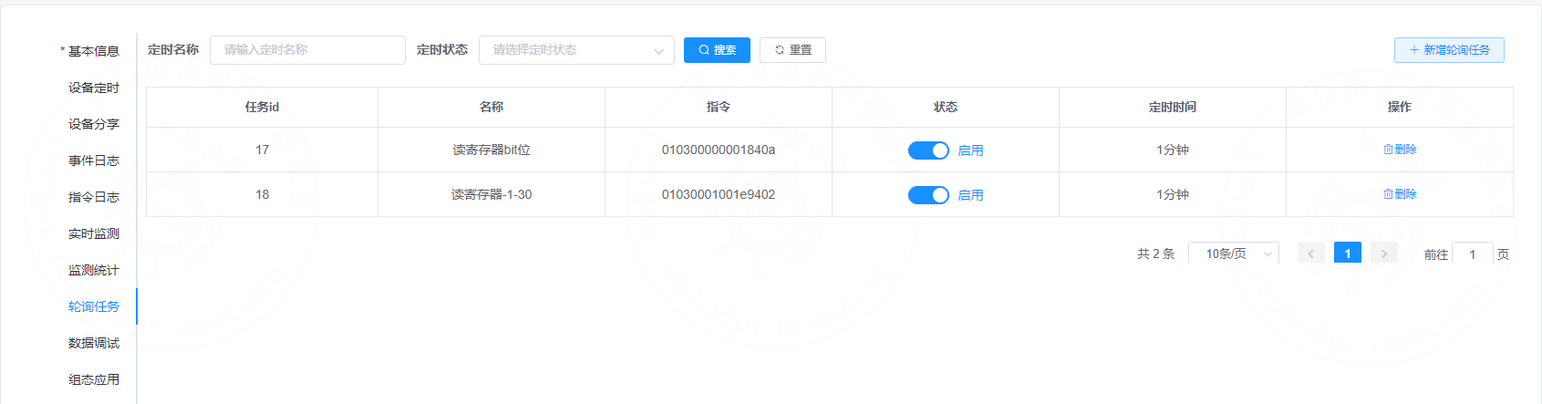
After the polling task is created, polling commands are automatically delivered when the gateway device comes online.
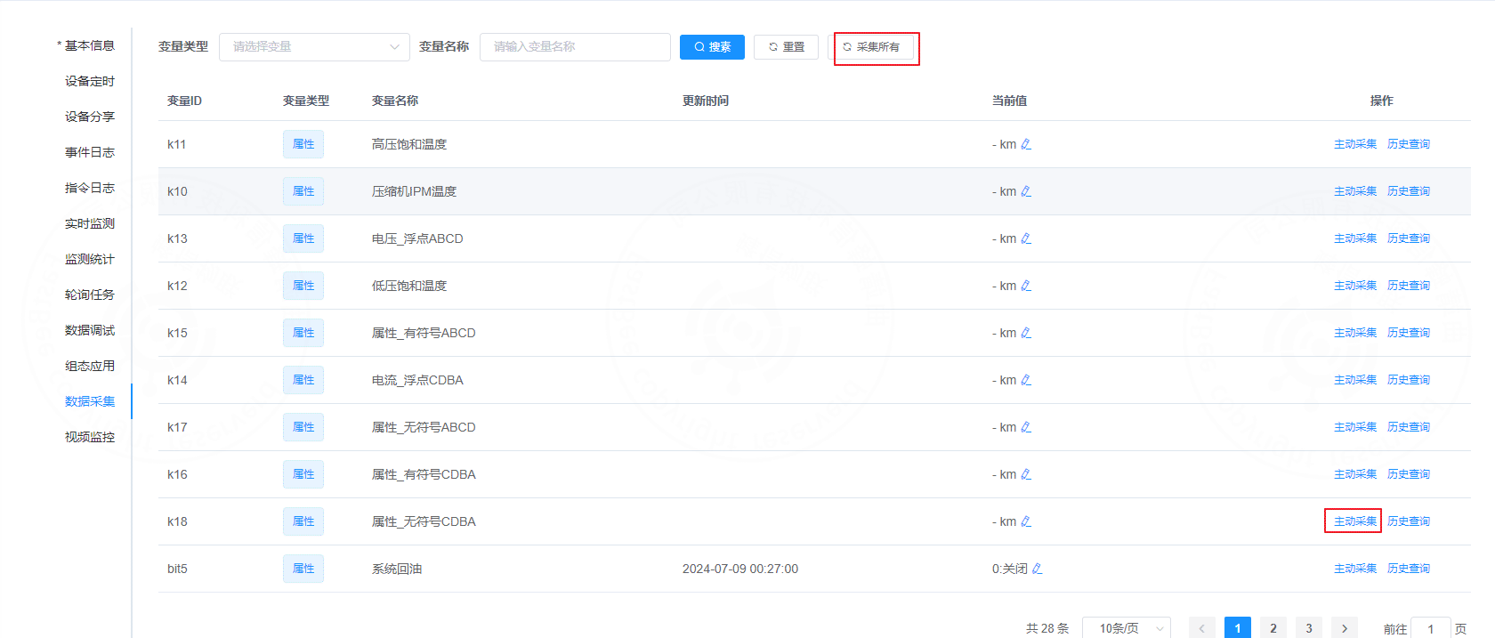
1.3 Active collection and collect all
Active collection immediately sends a read command and reads the register value corresponding to the selected thing model.
Collect all sends all polling commands and reads all configured register points.
2. Modbus protocol
2.1 Modbus RTU frame
A Modbus RTU message is one complete data frame. In essence, it is a complete sequence of instruction bytes.
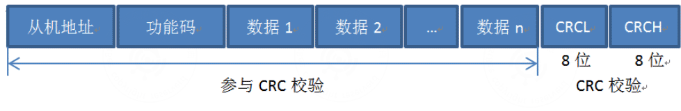
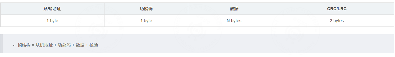
Frame fields:
- Slave address: each slave has a unique one-byte address. The full range is
0-255; the common valid slave range is1-247. Address255can be used as a broadcast address. - Function code: one byte. It defines what the instruction does, such as reading data or writing data.
- Data: varies by function code. For a read instruction, it usually contains the start address and the number of registers to read.
- CRC: cyclic redundancy check used to detect transmission errors.
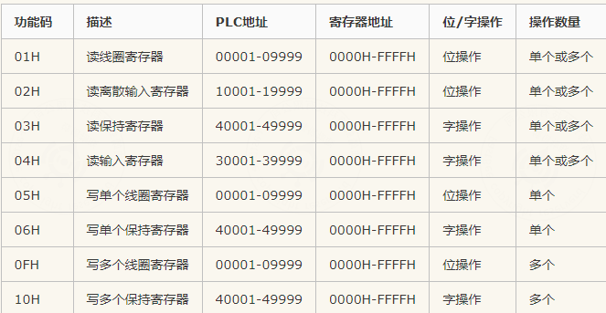
2.2 Modbus function codes
Modbus assigns a function code to each supported operation.
| Code | Meaning |
|---|---|
| 01H | Read coils |
| 02H | Read discrete inputs |
| 03H | Read holding registers |
| 04H | Read input registers |
| 05H | Write single coil |
| 06H | Write single register |
| 0FH | Write multiple coils |
| 10H | Write multiple registers |
2.3 Master reads data from slave

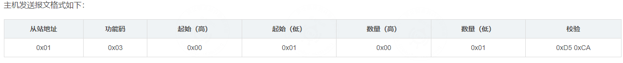
Example request:
01 03 00 01 00 01 D5 CAField explanation:
0x01: slave address.0x03: function code for reading holding registers.0x00 0x01: start register address. Reading starts from0x0001.0x00 0x01: number of registers to read.0xD5 0xCA: CRC.
Example response:
| Slave address | Function code | Byte count | Byte 1 | Byte 2 | CRC |
|---|---|---|---|---|---|
| 0x01 | 0x03 | 0x02 | 0x01 | 0x00 | 0xF8 0x4A |
Response explanation:
0x01: slave address.0x03: read function code.0x02: returned byte count is 2.0x00 0x17: register value.0xF8 0x4A: CRC.
2.4 Master writes data to slave
Example request:
01 06 00 01 00 17 98 04Field explanation:
0x01: slave address.0x06: function code for writing a single register.0x00 0x01: target register address.0x00 0x17: value to write.0x98 0x04: CRC.
The slave returns the same frame after a successful write.
0106000100179804| 0x01 | 06 | 00 01 | 00 17 | 98 04 |
|---|---|---|---|---|
| Slave address | Function code | Data address | Data | CRC |
2.5 Read command field example
0103020017F84A| 0x01 | 03 | 00 01 | 00 01 | D5 CA |
|---|---|---|---|---|
| Slave address | Function code | Data address | Number of values | CRC |
2.6 Message example
Read registers 40005 and 40006, assuming the slave address is 1.
Downstream message:
01 03 00 04 00 02 85 ca| Slave address | Function code | Start register address | Number of registers | CRC |
|---|---|---|---|---|
| 01 | 03 | 00 04 | 00 02 | 85 ca |
Upstream message:
01 03 04 00 00 00 00 21 33| Slave address | Function code | Returned byte count | Register 40005 data | Register 40006 data | CRC |
|---|---|---|---|---|---|
| 01 | 03 | 04 | 00 00 | 00 00 | 21 33 |
2.7 Common Modbus RTU function codes
| Data type | Read function code | Write function code | Object type |
|---|---|---|---|
| Discrete input | 02 | - | Single bit |
| Coil status | 01 | 05, 15 | Single bit |
| Input register | 04 | - | 16-bit word |
| Holding register | 03 | 06, 16 | 16-bit word |
2.8 Register start addresses
| Data type | Parameter address / register number |
|---|---|
| Discrete input | 00001-0FFFF |
| Coil status | 10001-1FFFF |
| Input register | 30001-3FFFF |
| Holding register | 40001-4FFFF |